
Datasheet


Section 5 Clock Pulse Generators
Rev. 3.00 Mar. 15, 2006 Page 69 of 526
REJ09B0060-0300
Section 5 Clock Pulse Generators
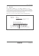
Clock oscillator circuitry (CPG: clock pulse generator) is provided on-chip, including both a
system clock pulse generator and a subclock pulse generator. The system clock pulse generator
consists of a system clock oscillator, a duty correction circuit, and system clock divider. The
subclock pulse generator consists of a subclock oscillator and a subclock divider.
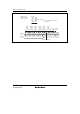
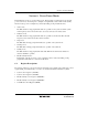
Figure 5.1 shows a block diagram of the clock pulse generators.
System
clock
oscillator
Subclock
oscillator
Subclock
divider
Duty
correction
circuit
System
clock
divider
Prescaler S
(13 bits)
Prescaler W
(5 bits)
OSC
1
OSC
2
X
1
X
2
System clock pulse generator
φ
OSC
(f
OSC
)
φ
OSC
(f
OSC
)
φ
W
(f
W
)
φ
W
/2
φ
W
/4
φ
SUB
φ/2
to
φ/8192
φ
W
/8
φ
φ
OSC
/8
φ
OSC
φ
OSC
/16
φ
OSC
/32
φ
OSC
/64
φ
W
/8
to
φ
W
/128
Subclock pulse generator
Figure 5.1 Block Diagram of Clock Pulse Generators
The basic clock signals that drive the CPU and on-chip peripheral modules are φ and φ
SUB
. The
system clock is divided by prescaler S to become a clock signal from φ/8192 to φ/2, and the
subclock is divided by prescaler W to become a clock signal from φw/128 to φw/8. Both the
system clock and subclock signals are provided to the on-chip peripheral modules.