
Datasheet


Section 15 Watchdog Timer
(WDT1 is not available in the H8S/2695)
Page 722 of 1434 R01UH0166EJ0600 Rev. 6.00
Mar 02, 2011
H8S/2633 Group, H8S/2633 F-ZTAT
TM
,
H8S/2633R F-ZTAT
TM
, H8S/2695
15.5.2 Changing Value of PSS and CKS2 to CKS0
If bits PSS and CKS2 to CKS0 in TCSR are written to while the WDT is operating, errors could
occur in the incrementation. Software must stop the watchdog timer (by clearing the TME bit to 0)
before changing the value of bits PSS and CKS2 to CKS0.
15.5.3 Switching between Watchdog Timer Mode and Interval Timer Mode
If the mode is switched from watchdog timer to interval timer, or vice versa, while the WDT is
operating, errors could occur in the incrementation. Software must stop the watchdog timer (by
clearing the TME bit to 0) before switching the mode.
15.5.4 System Reset by WDTOVF Signal
If the WDTOVF output signal is input to the RES pin of the H8S/2633 Group, the H8S/2633
Group will not be initialized correctly. Make sure that the WDTOVF signal is not input logically
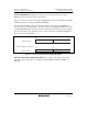
to the RES pin. To reset the entire system by means of the WDTOVF signal, use the circuit shown
in figure 15.9.
Reset input
Reset signal to entire system
H8S/2633 Group
RES
WDTOVF
Figure 15.9 Circuit for System Reset by WDTOVF Signal (Example)
15.5.5 Internal Reset in Watchdog Timer Mode
The H8S/2633 Group is not reset internally if TCNT overflows while the RSTE bit is cleared to 0
during watchdog timer operation, but TCNT and TCSR of the WDT are reset.
TCNT, TCSR, and RSTCSR cannot be written to while the WDTOVF signal is low. Also note
that a read of the WOVF flag is not recognized during this period. To clear the WOVF falg,
therefore, read RSTCSR after the WDTOVF signal goes high, then write 0 to the WOVF flag.