
Datasheet


Section 11 16-Bit Timer Pulse Unit (TPU)
Page 600 of 1434 R01UH0166EJ0600 Rev. 6.00
Mar 02, 2011
H8S/2633 Group, H8S/2633 F-ZTAT
TM
,
H8S/2633R F-ZTAT
TM
, H8S/2695
11.4.5 Cascaded Operation
In cascaded operation, two 16-bit counters for different channels are used together as a 32-bit
counter.
This function works by counting the channel 1 (channel 4) counter clock upon overflow/underflow
of TCNT2 (TCNT5) as set in bits TPSC2 to TPSC0 in TCR.
Underflow occurs only when the lower 16-bit TCNT is in phase-counting mode.
Table 11.6 shows the register combinations used in cascaded operation.
Note: When phase counting mode is set for channels 1 or 4, the counter clock setting is invalid
and the counter operates independently in phase counting mode.
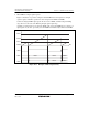
Table 11.6 Cascaded Combinations
Combination Upper 16 Bits Lower 16 Bits
Channels 1 and 2 TCNT1 TCNT2
Channels 4 and 5 TCNT4 TCNT5
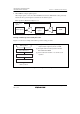
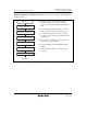
Example of Cascaded Operation Setting Procedure: Figure 11.21 shows an example of the
setting procedure for cascaded operation.
Set cascading
Cascaded operation
Start count
<Cascaded operation>
[1]
[2]
[1] Set bits TPSC2 to TPSC0 in the channel 1
(channel 4) TCR to B'111 to select TCNT2
(TCNT5) overflow/underflow counting.
[2] Set the CST bit in TSTR for the upper and lower
channel to 1 to start the count operation.
Figure 11.21 Cascaded Operation Setting Procedure