
Datasheet


Appendix B Internal I/O Registers
Rev.7.00 Feb. 14, 2007 page 961 of 1108
REJ09B0089-0700
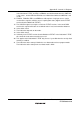
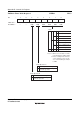
TCR3—Timer Control Register 3 H'FE80 TPU3
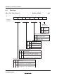
7
CCLR2
0
R/W
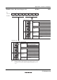
6
CCLR1
0
R/W
5
CCLR0
0
R/W
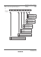
4
CKEG1
0
R/W
3
CKEG0
0
R/W
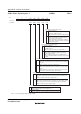
0
TPSC0
0
R/W
2
TPSC2
0
R/W
1
TPSC1
0
R/W
Bit
Initial value
Read/Write
:
:
:
TCNT clearing disabled
TCNT cleared by TGRA compare match/input capture
TCNT cleared by TGRB compare match/input capture
TCNT clearing disabled
TCNT cleared by TGRC compare match/input capture
*2
TCNT cleared by TGRD compare match/input capture
*2
Counter Clear
0
1
0
1
0
1
0
1
0
1
0
1
0
1
0
1
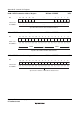
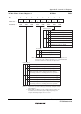
Clock Edge
0
1
⎯
Count at rising edge
Count at falling edge
Count at both edges
Internal clock: counts on φ/1
Internal clock: counts on φ/4
Internal clock: counts on φ/16
Internal clock: counts on φ/64
External clock: counts on
TCLKA pin input
Internal clock: counts on φ/1024
Internal clock: counts on φ/256
Internal clock: counts on φ/4096
Timer Prescaler
0
1
0
1
0
1
0
1
0
1
0
1
0
1
TCNT cleared by counter clearing for another channel
performing synchronous clearing/synchronous operation
*1
TCNT cleared by counter clearing for another channel
performing synchronous clearing/synchronous operation
*1
Notes: 1.
2.
Synchronous operation setting is performed by setting the SYNC
bit in TSYR to 1.
When TGRC or TGRD is used as a buffer register, TCNT is not
cleared because the buffer register setting has priority,
and
compare match/input capture does not occur.
Note:
The internal clock edge selection is valid when the input clock is
φ/4 or slower. This setting is ignored if φ/1 or overflow/underflow
on another channel is selected as the input clock.