
Datasheet


Section 11 Watchdog Timer
Rev.7.00 Feb. 14, 2007 page 419 of 1108
REJ09B0089-0700
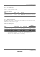
11.2.2 Timer Control/Status Register (TCSR)
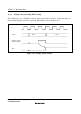
Bit : 7 6 5 4 3 2 1 0
OVF WT/IT TME — — CKS2 CKS1 CKS0
Initial value : 0 0 0 1 1 0 0 0
R/W : R/(W)
*
R/W R/W — — R/W R/W R/W
Note: * Only 0 can be written, to clear the flag.
TCSR is an 8-bit readable/writable
*
register. Its functions include selecting the clock source to be
input to TCNT, and the timer mode.
TCR is initialized to H'18 by a reset and in hardware standby mode. It is not initialized in software
standby mode.
Note: * TCSR is write-protected by a password to prevent accidental overwriting. For details see
section 11.2.4, Notes on Register Access.
Bit 7—Overflow Flag (OVF): Indicates that TCNT has overflowed from H'FF to H'00, when in
interval timer mode. This flag cannot be set during watchdog timer operation.
Bit 7
OVF
Description
0 [Clearing condition] (Initial value)
Cleared by reading TCSR when OVF = 1
*
, then writing 0 to OVF
1 [Setting condition]
Set when TCNT overflows (changes from H'FF to H'00) in interval timer mode
Note: * When OVF is polled and the interval timer interrupt is disabled, OVF = 1 must be read at
least twice.
Bit 6—Timer Mode Select (WT/IT): Selects whether the WDT is used as a watchdog timer or
interval timer. If used as an interval timer, the WDT generates an interval timer interrupt request
(WOVI) when TCNT overflows. If used as a watchdog timer, the WDT generates the WDTOVF
signal
*
1
when TCNT overflows.