
Datasheet


Section 20 Electrical Characteristics
Rev.7.00 Feb. 14, 2007 page 861 of 1108
REJ09B0089-0700
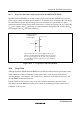
20.3.7 Usage Note (Internal voltage step down for the H8S/2319C F-ZTAT)
The H8S/2319C F-ZTAT has an on-chip voltage step down circuit that automatically lowers the
power supply voltage, inside the microcomputer, to an adequate level. A capacitor (0.1 µF) should
be connected between the internal voltage step down circuit pin (V
CL
pin) and the V
SS
pin to
stabilize the internal voltage. Figure 20.23 shows how to connect the capacitor. Do not connect the
V
CC
power supply to the V
CL
pin. Doing so could permanently damage the LSI. (Connect the V
CC
power-supply to the V
CC
pin, in the usual way.)
V
CL
V
SS
External capacitor
to stabilize the
power supply
Do not connect the V
CC
power-supply to the V
CL
pin.
Doing so could permanently damage the LSI. (Connect
the V
CC
power-supply to the V
CC
pin, in the usual way.)
Use a multilayer ceramic capacitor (0.1 μF), and place
it near the pins.
0.1 μF
Figure 20.23 V
CL
Capacitor Connection Method
20.4 Usage Note
Although both the F-ZTAT and mask ROM versions fully meet the electrical specifications listed
in this manual, there may be differences in the actual values of the electrical characteristics,
operating margins, noise margins, and so forth, due to differences in the fabrication process, the
on-chip ROM, and the layout patterns.
If the F-ZTAT version is used to carry out system evaluation and testing, therefore, when
switching to the mask ROM version the same evaluation and testing procedures should also be
conducted on this version.