
Datasheet


Section 18 Clock Pulse Generator
Rev.7.00 Feb. 14, 2007 page 798 of 1108
REJ09B0089-0700
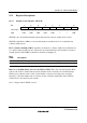
18.3.2 External Clock Input
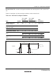
Circuit Configuration: An external clock signal can be input as shown in the examples in figure
18.5. If the XTAL pin is left open, make sure that stray capacitance is no more than 10 pF.
In example (b), make sure that the external clock is held high in standby mode.
EXTAL
XTAL
External clock inpu
t
Open
(a) XTAL pin left open
EXTAL
XTAL
External clock inpu
t
(b) Complementary clock input at XTAL pin
Figure 18.5 External Clock Input (Examples)