
Datasheet


Section 17 ROM
Rev.7.00 Feb. 14, 2007 page 671 of 1108
REJ09B0089-0700
H8S/2319 F-ZTAT
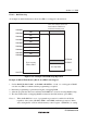
Socket Adapter
(40-Pin Conversion)
TFP-100B FP-100A
Pin Name
32
33
34
35
36
37
38
39
41
42
43
44
45
46
47
48
50
51
52
53
99
23
24
25
26
27
28
29
30
55
54
56
60
34
35
36
37
38
39
40
41
43
44
45
46
47
48
49
50
52
53
54
55
1
25
26
27
28
29
30
31
32
57
56
58
62
A
0
A
1
A
2
A
3
A
4
A
5
A
6
A
7
A
8
A
9
A
10
A
11
A
12
A
13
A
14
A
15
A
16
A
17
A
18
A
19
A
20
D
8
D
9
D
10
D
11
D
12
D
13
D
14
D
15
CE
OE
WE
EMLE
*3
HN27C4096HG (40 Pins)
Pin No.
Pin Name
21
22
23
24
25
26
27
28
29
31
32
33
34
35
36
37
38
39
10
9
8
19
18
17
16
15
14
13
12
2
20
3
4
1, 40
11, 30
5, 6, 7
A
0
A
1
A
2
A
3
A
4
A
5
A
6
A
7
A
8
A
9
A
10
A
11
A
12
A
13
A
14
A
15
A
16
A
17
A
18
A
19
A
20
I/O
0
I/O
1
I/O
2
I/O
3
I/O
4
I/O
5
I/O
6
I/O
7
CE
OE
WE
FWE
V
CC
V
SS
NC
64
68
69
62
66
67
RES
XTAL
EXTAL
NC (OPEN)
40, 63, 64, 65, 74,
77, 78, 98, 59
42, 65, 66, 67, 76,
79, 80, 100, 61
9, 20, 33, 51, 59,
60, 63, 70, 77,
78, 89, 90, 92
7, 18, 31, 49, 57,
58, 61, 68, ,75,
76, 87, 88, 90
V
SS
V
CC
Reset circuit
Oscillation circuit
*1
*2
Legend:
EMLE: Emulation enable
I/O
7
to I/O
0
: Data input/output
A
18
to A
0
: Address input
CE: Chip enable
OE: Output enable
WE: Write enable
Notes: This figure shows pin assignments, and does not show the entire socket adapter circuit.
1. A reset oscillation stabilization time (t
osc1
) of at least 10 ms is required.
2. A 12-MHz crystal resonator should be used.
3. As the FWE pin becomes
V
CC
in the H8S/2319 F-ZTAT, the EMLE pin is ignored in programmer mode.
Other pins
Figure 17.51 H8S/2319F-ZTAT Socket Adapter Pin Assignments