
Datasheet


Section 17 ROM
Rev.7.00 Feb. 14, 2007 page 572 of 1108
REJ09B0089-0700
• Programmer mode
Flash memory can be programmed/erased in programmer mode, using a PROM programmer,
as well as in on-board programming mode.
Note: * Flash memory emulation by RAM is not supported in the H8S/2314 F-ZTAT.
17.4.2 Overview
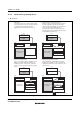
Block Diagram
Module bus
Bus interface/controller
Flash memory
(128, 256, 384 kbytes)
Operating
mode
EBR1
Internal address bus
Internal data bus (16 bits)
FWE pin
Mode pins
EBR2
SYSCR2
FLMCR2
FLMCR1
RAMER
Legend:
FLMCR1: Flash memory control register 1
FLMCR2: Flash memory control register 2
EBR1: Erase block register 1
EBR2: Erase block register 2
RAMER: RAM emulation register
SYSCR2: System control register 2
Figure 17.2 Block Diagram of Flash Memory