
Datasheet


Section 14 A/D Converter (8 Analog Input Channel Version)
Rev.7.00 Feb. 14, 2007 page 536 of 1108
REJ09B0089-0700
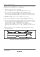
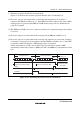
14.2.2 A/D Control/Status Register (ADCSR)
Bit : 7 6 5 4 3 2 1 0
ADF ADIE ADST SCAN CKS CH2 CH1 CH0
Initial value : 0 0 0 0 0 0 0 0
R/W : R/(W)
*
R/W R/W R/W R/W R/W R/W R/W
Note: * Only 0 can be written to bit 7, to clear this flag.
ADCSR is an 8-bit readable/writable register that controls A/D conversion operations and shows
the status of the operation.
ADCSR is initialized to H'00 by a reset, and in standby mode or module stop mode.
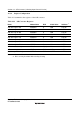
Bit 7—A/D End Flag (ADF): Status flag that indicates the end of A/D conversion.
Bit 7
ADF
Description
0 [Clearing conditions] (Initial value)
• When 0 is written to the ADF flag after reading ADF = 1
• When the DTC is activated by an ADI interrupt and ADDR is read
1 [Setting conditions]
• Single mode: When A/D conversion ends
• Scan mode: When A/D conversion ends on all specified channels
Bit 6—A/D Interrupt Enable (ADIE): Selects enabling or disabling of interrupt (ADI) requests
at the end of A/D conversion.
Bit 6
ADIE
Description
0 A/D conversion end interrupt (ADI) request disabled (Initial value)
1 A/D conversion end interrupt (ADI) request enabled