
Datasheet


Section 13 Smart Card Interface
Rev.7.00 Feb. 14, 2007 page 504 of 1108
REJ09B0089-0700
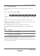
Bit 2
SINV
Description
0 TDR contents are transmitted as they are (Initial value)
Receive data is stored as it is in RDR
1 TDR contents are inverted before being transmitted
Receive data is stored in inverted form in RDR
Bit 1—Reserved: Read-only bit, always read as 1.
Bit 0—Smart Card Interface Mode Select (SMIF): Enables or disables the smart card interface
function.
Bit 0
SMIF
Description
0 Smart card interface function is disabled (Initial value)
1 Smart card interface function is enabled
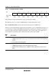
13.2.2 Serial Status Register (SSR)
Bit : 7 6 5 4 3 2 1 0
TDRE RDRF ORER ERS PER TEND MPB MPBT
Initial value : 1 0 0 0 0 1 0 0
R/W : R/(W)
*
R/(W)
*
R/(W)
*
R/(W)
*
R/(W)
*
R R R/W
Note: * Only 0 can be written to bits 7 to 3, to clear these flags.
Bit 4 of SSR has a different function in smart card interface mode. Coupled with this, the setting
conditions for bit 2, TEND, are also different.
Bits 7 to 5—Operate in the same way as for the normal SCI. For details, see section 12.2.7, Serial
Status Register (SSR).
Bit 4—Error Signal Status (ERS): In smart card interface mode, bit 4 indicates the status of the
error signal sent back from the receiving end in transmission. Framing errors are not detected in
smart card interface mode.