
Datasheet


Section 11 Watchdog Timer
Rev.7.00 Feb. 14, 2007 page 416 of 1108
REJ09B0089-0700
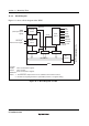
11.1.2 Block Diagram
Figure 11.1 shows a block diagram of the WDT.
Overflow
Interrupt
control
WOVI
(interrupt request
signal)
WDTOVF
*1
Internal reset signal
*2
Reset
control
RSTCSR TCNT TSCR
φ/2
φ/64
φ/128
φ/512
φ/2048
φ/8192
φ/32768
φ/131072
Clock
Clock
select
Internal clock
sources
Bus
interface
Module bus
Legend:
TCSR:
TCNT:
RSTCSR:
Notes:
Timer control/status register
Timer counter
Reset control/status register
Internal bus
WDT
1. The WDTOVF output function is not available in the F-ZTAT versions.
2. Internal reset signal generation is specified by means of a register setting.
Figure 11.1 Block Diagram of WDT