
Datasheet


Section 10 8-Bit Timers
Rev.7.00 Feb. 14, 2007 page 404 of 1108
REJ09B0089-0700
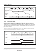
10.3.3 Timing of TCNT External Reset
TCNT is cleared at the rising edge of an external reset input, depending on the settings of the
CCLR1 and CCLR0 bits in TCR. The clear pulse width must be at least 1.5 states. Figure 10.7
shows the timing of this operation.
φ
Clear signal
External reset
input pin
TCNT N H'00N−1
Figure 10.7 Timing of Clearance by External Reset
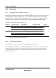
10.3.4 Timing of Overflow Flag (OVF) Setting
The OVF in TCSR is set to 1 when TCNT overflows (changes from H'FF to H'00). Figure 10.8
shows the timing of this operation.
φ
OVF
Overflow signal
TCNT H'FF H'00
Figure 10.8 Timing of OVF Setting