
Datasheet


Section 9 16-Bit Timer Pulse Unit (TPU)
Rev.7.00 Feb. 14, 2007 page 361 of 1108
REJ09B0089-0700
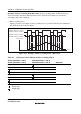
Figure 9.26 shows an example of PWM mode 2 operation.
In this example, synchronous operation is designated for channels 0 and 1, TGR1B compare
match is set as the TCNT clearing source, and 0 is set for the initial output value and 1 for the
output value of the other TGR registers (TGR0A to TGR0D, TGR1A), to output a 5-phase PWM
waveform.
In this case, the value set in TGR1B is used as the period, and the values set in the other TGR
registers as the duty.
TCNT value
TGR1B
H'0000
TIOCA0
Counter cleared by TGR1B
compare match
TGR1A
TGR0D
TGR0C
TGR0B
TGR0A
TIOCB0
TIOCC0
TIOCD0
TIOCA1
Time
Figure 9.26 Example of PWM Mode Operation (2)