
Datasheet


Section 9 16-Bit Timer Pulse Unit (TPU)
Rev.7.00 Feb. 14, 2007 page 350 of 1108
REJ09B0089-0700
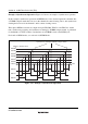
Example of Synchronous Operation: Figure 9.15 shows an example of synchronous operation.
In this example, synchronous operation and PWM mode 1 have been designated for channels 0 to
2, TGR0B compare match has been set as the channel 0 counter clearing source, and synchronous
clearing has been set for the channel 1 and 2 counter clearing sources.
Three-phase PWM waveforms are output from pins TIOC0A, TIOC1A, and TIOC2A. At this
time, synchronous presetting, and synchronous clearing by TGR0B compare match, is performed
for channel 0 to 2 TCNT counters, and the data set in TGR0B is used as the PWM cycle.
For details of PWM modes, see section 9.4.6, PWM Modes.
TCNT0 to TCNT2 values
H'0000
TIOC0A
TIOC1A
Time
TGR0B
Synchronous clearing by TGR0B compare match
TGR2A
TGR1A
TGR2B
TGR0A
TGR1B
TIOC2A
Figure 9.15 Example of Synchronous Operation