
Datasheet


Section 9 16-Bit Timer Pulse Unit (TPU)
Rev.7.00 Feb. 14, 2007 page 333 of 1108
REJ09B0089-0700
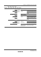
9.2.5 Timer Status Registers (TSR)
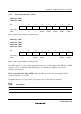
Channel 0: TSR0
Channel 3: TSR3
Bit : 7 6 5 4 3 2 1 0
— — — TCFV TGFD TGFC TGFB TGFA
Initial value : 1 1 0 0 0 0 0 0
R/W : — — — R/(W)
*
R/(W)
*
R/(W)
*
R/(W)
*
R/(W)
*
Note: * Only 0 can be written, to clear the flag.
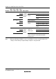
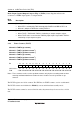
Channel 1: TSR1
Channel 2: TSR2
Channel 4: TSR4
Channel 5: TSR5
Bit : 7 6 5 4 3 2 1 0
TCFD — TCFU TCFV — — TGFB TGFA
Initial value : 1 1 0 0 0 0 0 0
R/W : R — R/(W)
*
R/(W)
*
— — R/(W)
*
R/(W)
*
Note: * Only 0 can be written, to clear the flag.
The TSR registers are 8-bit registers that indicate the status of each channel. The TPU has six TSR
registers, one for each channel. The TSR registers are initialized to H'C0 by a reset and in
hardware standby mode.
Bit 7—Count Direction Flag (TCFD): Status flag that shows the direction in which TCNT
counts in channels 1, 2, 4, and 5.
In channels 0 and 3, bit 7 is reserved. It is always read as 1 and cannot be modified.
Bit 7
TCFD
Description
0 TCNT counts down
1 TCNT counts up (Initial value)