
Datasheet


Section 8 I/O Ports
Rev.7.00 Feb. 14, 2007 page 260 of 1108
REJ09B0089-0700
8.7.2 Register Configuration
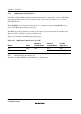
Table 8.11 shows the port B register configuration.
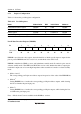
Table 8.11 Port B Registers
Name Abbreviation R/W Initial Value Address
*
Port B data direction register PBDDR W H'00 H'FEBA
Port B data register PBDR R/W H'00 H'FF6A
Port B register PORTB R Undefined H'FF5A
Port B MOS pull-up control register PBPCR R/W H'00 H'FF71
Note: * Lower 16 bits of the address.
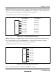
Port B Data Direction Register (PBDDR)
Bit : 7 6 5 4 3 2 1 0
PB7DDR PB6DDR PB5DDR PB4DDR PB3DDR PB2DDR PB1DDR PB0DDR
Initial value : 0 0 0 0 0 0 0 0
R/W : W W W W W W W W
PBDDR is an 8-bit write-only register, the individual bits of which specify input or output for the
pins of port B. PBDDR cannot be read; if it is, an undefined value will be read.
PBDDR is initialized to H'00 by a reset, and in hardware standby mode. It retains its prior state in
software standby mode. The OPE bit in SBYCR is used to select whether the address output pins
retain their output state or become high-impedance when a transition is made to software standby
mode.
• Modes 4 and 5
The corresponding port B pins are address outputs irrespective of the value of the PBDDR bits.
• Mode 6
*
Setting PBDDR bits to 1 makes the corresponding port B pins address outputs, while clearing
the bits to 0 makes the pins input ports.
• Mode 7
*
Setting PBDDR bits to 1 makes the corresponding port B pins outputs, while clearing the bits
to 0 makes the pins input ports.
Note: * Modes 6 and 7 are not available in the ROMless versions.