
Datasheet


Section 7 Data Transfer Controller
Rev.7.00 Feb. 14, 2007 page 184 of 1108
REJ09B0089-0700
7.1.2 Block Diagram
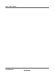
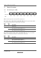
Figure 7.1 shows a block diagram of the DTC.
The DTC’s register information is stored in the on-chip RAM
*
. A 32-bit bus connects the DTC to
the on-chip RAM (1 kbyte), enabling 32-bit, 1-state reading and writing of DTC register
information.
Note: * When the DTC is used, the RAME bit in SYSCR must be set to 1.
Interrupt
request
Interrupt controller DTC
Internal address bus
DTC activation
request
Control logic
Register information
MRA MRB
CRA
CRB
DAR
SAR
CPU interrupt
request
On-chip
RAM
Internal data bus
Legend:
MRA, MRB:
CRA, CRB:
SAR:
DAR:
DTCERA to DTCERE:
DTVECR:
DTCERA
to
DTCERE
DTVECR
DTC mode registers A and B
DTC transfer count registers A and B
DTC source address register
DTC destination address register
DTC enable registers A to E
DTC vector register
Figure 7.1 Block Diagram of DTC