
Datasheet


Section 6 Bus Controller
Rev.7.00 Feb. 14, 2007 page 140 of 1108
REJ09B0089-0700
6.1.2 Block Diagram
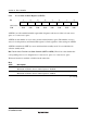
Figure 6.1 shows a block diagram of the bus controller.
Area decoder
Bus
controller
ABWCR
ASTCR
BCRH
BCRL
Internal
address bus
CS0 to CS7
External bus control signals
BREQ
BACK
BREQO
Internal control
signals
Wait
controller
WCRH
WCRL
Bus mode signal
Bus arbiter
CPU bus request signal
DTC bus request signal
CPU bus acknowledge signal
DTC bus acknowledge signal
WAIT
Internal data bus
Figure 6.1 Block Diagram of Bus Controller