
Datasheet


Section 5 Interrupt Controller
Rev.7.00 Feb. 14, 2007 page 112 of 1108
REJ09B0089-0700
5.2 Register Descriptions
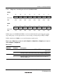
5.2.1 System Control Register (SYSCR)
Bit : 7 6 5 4 3 2 1 0
— — INTM1 INTM0 NMIEG LWROD — RAME
Initial value : 0 0 0 0 0 0 0 1
R/W : R/W — R/W R/W R/W R/W R/W R/W
SYSCR is an 8-bit readable/writable register that selects the interrupt control mode, and the
detected edge for NMI.
Only bits 5 to 3 are described here; for details of the other bits, see section 3, MCU Operating
Modes.
SYSCR is initialized to H'01 by a reset and in hardware standby mode. It is not initialized in
software standby mode.
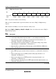
Bits 5 and 4—Interrupt Control Mode 1 and 0 (INTM1, INTM0): These bits select one of two
interrupt control modes for the interrupt controller.
Bit 5
INTM1
Bit 4
INTM0
Interrupt
Control Mode
Description
0 0 0 Interrupts are controlled by I bit (Initial value)
1 — Setting prohibited
1 0 2 Interrupts are controlled by bits I2 to I0, and IPR
1 — Setting prohibited
Bit 3—NMI Edge Select (NMIEG): Selects the input edge for the NMI pin.
Bit 3
NMIEG
Description
0 Interrupt request generated at falling edge of NMI input (Initial value)
1 Interrupt request generated at rising edge of NMI input