
Datasheet


Section 4 Exception Handling
Rev.7.00 Feb. 14, 2007 page 100 of 1108
REJ09B0089-0700
4.1.2 Exception Handling Operation
Exceptions originate from various sources. Trap instructions and interrupts are handled as
follows:
1. The program counter (PC), condition code register (CCR), and extend register (EXR) are
pushed onto the stack.
2. The interrupt mask bits are updated. The T bit is cleared to 0.
3. A vector address corresponding to the exception source is generated, and program execution
starts from that address.
For a reset exception, steps 2 and 3 above are carried out.
4.1.3 Exception Vector Table
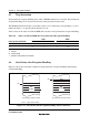
The exception sources are classified as shown in figure 4.1. Different vector addresses are
assigned to different exception sources.
Table 4.2 lists the exception sources and their vector addresses.
Exception
sources
• Reset
• Trace
• Interrupts
• Trap instruction
External interrupts: NMI, IRQ7 to IRQ0
Internal interrupts: interrupts from on-chip
supporting modules
Figure 4.1 Exception Sources
In modes 6 and 7, the on-chip ROM available for use after a power-on reset is the 64-kbyte area
comprising addresses H'000000 to H'00FFFF. Care is required when setting vector addresses. In
this case, clearing the EAE bit in BCRL enables the 256-kbyte (128 kbytes/384 kbytes/512 kbytes)
area
*
comprising addresses H'000000 to H'03FFFF (to H'01FFFF/H'05FFFF/H'07FFFF) to be
used.
Note: * The different have different amounts of on-chip ROM. For details, see section 6.2.5, Bus
Control Register L (BCRL).