
Datasheet


Appendix B Internal I/O Registers
Rev.7.00 Feb. 14, 2007 page 1057 of 1108
REJ09B0089-0700
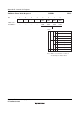
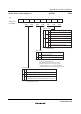
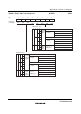
TCR1—Timer Control Register 1 H'FFE0 TPU1
TCNT clearing disabled
TCNT cleared by TGRA compare match/input capture
TCNT cleared by TGRB compare match/input capture
Counter Clear
0
1
0
1
0
1
0
1
Clock Edge*
0
1
⎯
Count at rising edge
Count at falling edge
Count at both edges
Internal clock: counts on φ/1
Internal clock: counts on φ/4
Internal clock: counts on φ/16
Internal clock: counts on φ/6
4
External clock: counts on TCLKA pin input
External clock: counts on TCLKB pin input
Internal clock: counts on φ/256
Counts on TCNT2 overflow/underflow
Time Prescaler
0
1
0
1
0
1
0
1
0
1
0
1
0
1
7
⎯
0
⎯
6
CCLR1
0
R/W
5
CCLR0
0
R/W
4
CKEG1
0
R/W
3
CKEG0
0
R/W
0
TPSC0
0
R/W
2
TPSC2
0
R/W
1
TPSC1
0
R/W
Note:
This setting is ignored when channel 1 is in phase
counting mode.
Note: * Synchronous operation setting is performed by setting
the SYNC bit in TSYR to 1.
Bit
Initial value
Read/Write
:
:
:
Note: *
This setting is ignored when channel
1 is in phase counting mode.
The internal clock edge selection is
valid when the input clock is φ/4 or slower. This setting
is ignored if φ/1 or
overflow/underflow on another channel
is selected as the input clock.
TCNT cleared by counter clearing for another channel
performing synchronous clearing/synchronous operation*