
Datasheet


Section 3 MCU Operating Modes
Rev.7.00 Feb. 14, 2007 page 71 of 1108
REJ09B0089-0700
Section 3 MCU Operating Modes
3.1 Overview
3.1.1 Operating Mode Selection (H8S/2318 F-ZTAT, H8S/2317 F-ZTAT,
H8S/2315 F-ZTAT, and H8S/2314 F-ZTAT)
The H8S/2318 F-ZTAT, H8S/2317 F-ZTAT, H8S/2315 F-ZTAT, and H8S/2314 F-ZTAT have
eight operating modes (modes 4 to 7, 10, 11, 14 and 15). These modes are determined by the mode
pin (MD2 to MD0) and flash write enable pin (FWE) settings. The CPU operating mode and
initial bus width can be selected as shown in table 3.1.
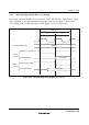
Table 3.1 lists the MCU operating modes.
Table 3.1 MCU Operating Mode Selection (H8S/2318 F-ZTAT, H8S/2317 F-ZTAT,
H8S/2315 F-ZTAT, and H8S/2314 F-ZTAT)
External Data
Bus
MCU
Operating
Mode
FWE
MD2
MD1
MD0
CPU
Operating
Mode
Description
On-Chip
ROM
Initial
Value
Max.
Value
1
*
0 0 0 1 — — — — —
2
*
1 0
3
*
1
4 1 0 0 Advanced Disabled 16 bits 16 bits
5 1
Expanded mode with
on-chip ROM disabled
8 bits 16 bits
6 1 0
Expanded mode with
on-chip ROM enabled
Enabled 8 bits 16 bits
7 1 Single-chip mode — —
8
*
1 0 0 0 — — — — —
9
*
1
10 1 0 Advanced Boot mode Enabled 8 bits 16 bits
11 1 — —
12
*
1 0 0 — — — — —
13
*
1
14 1 0 Advanced User program mode Enabled 8 bits 16 bits
15 1 — —
Note: * Cannot be used in this LSI.