
Datasheet


Appendix B Internal I/O Registers
Rev.7.00 Feb. 14, 2007 page 1012 of 1108
REJ09B0089-0700
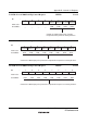
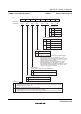
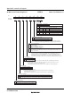
SMR0—Serial Mode Register 0 H'FF78 SCI0
7
C/A
0
R/W
6
CHR
0
R/W
5
PE
0
R/W
4
O/E
0
R/W
3
STOP
0
R/W
0
CKS0
0
R/W
2
MP
0
R/W
1
CKS1
0
R/W
0
1
Asynchronous mode
Synchronous mode
Asynchronous Mode/Synchronous Mode Select
0
1
Parity bit addition and checking disabled
Parity bit addition and checking enabled*
Parity Enable
0
1
Even parity
*1
Odd parity
*2
Parity Mode
0
1
Multiprocessor function disabled
Multiprocessor format selected
1. When even parity is selected, the parity bit added to
transmit data makes an even number of 1s in the
transmitted character and parity bit combined. Receive
data must have an even number of 1s in the received
character and parity bit combined.
2. When odd parity is selected, the parity bit added to
transmit data makes an odd number of 1s in the
transmitted character and parity bit combined. Receive
data must have an odd number of 1s in the received
character and parity bit combined.
Multiprocessor Mode
0
1
1 stop bit
2 stop bits
Stop Bit Length
Notes:
* When the PE bit is set to 1, the parity (even or odd) specified by
the O/E bit is added to transmit data before transmission. In
reception, the parity bit is checked for the parity (even or odd)
specified by the O/E bit.
Note:
0
1
0
1
0
1
φ clock
φ/4 clock
φ/16 clock
φ/64 clock
Clock Select
0
1
8-bit data
7-bit data*
Character Length
Bit
Initial value
Read/Write
:
:
:
Note: * When 7-bit data is selected, the MSB (bit 7) of TDR is not transmitted.
With 7-bit data, it is not possible to select LSB-first or MSB-first transfer.