
Datasheet


Section 20 Electrical Characteristics
Rev.7.00 Feb. 14, 2007 page 850 of 1108
REJ09B0089-0700
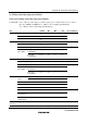
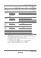
Notes: 1. Follow the program/erase algorithms when making the time settings.
2. Programming time per 128 bytes. (In the H8S/2318, H8S/2317, H8S/2315, and
H8S/2314, indicates the total time during which the P bit in flash memory control
register 1 (FLMCR1) is set. In the H8S/2319, indicates the total time during which the
P1 bit and P2 bit in the flash memory control registers (FLMCR1, FLMCR2) are set.
Does not include the program-verify time.)
3. Time to erase one block. (In the H8S/2318, H8S/2317, H8S/2315, and H8S/2314,
indicates the total time during which during which the E1 bit in FLMCR1 and the E2 bit
in FLMCR2 are set. Does not include the erase-verify time.)
4. Maximum programming time
Σ wait time after P bit setting (z)
N
t
P
(max) =
i=1
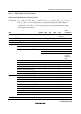
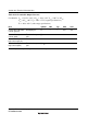
5. The maximum number of writes (N) should be set as shown below according to the
actual set value of z so as not to exceed the maximum programming time (t
P
(max)).
The wait time after P bit setting (z) should be changed as follows according to the
number of writes (n).
Number of writes (n)
1 ≤ n ≤ 6 z = 30 μs
7 ≤ n ≤ 1000 z = 200 μs
[In additional programming]
Number of writes (n)
1 ≤ n ≤ 6 z = 10 μs
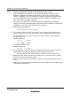
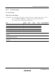
6. For the maximum erase time (t
E
(max)), the following relationship applies between the
wait time after E bit setting (z) and the maximum number of erases (N):
t
E
(max) = Wait time after E bit setting (z) × maximum number of erases (N)
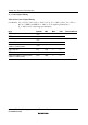
7. Minimum number of times for which all characteristics are guaranteed after rewriting
(Guarantee range is 1 to minimum value).
8. Reference value for 25°C (as a guideline, rewriting should normally function up to this
value).
9. Data retention characteristic when rewriting is performed within the specification range,
including the minimum value.