
Datasheet

Section 19 Power-Down Modes
Rev.7.00 Feb. 14, 2007 page 802 of 1108
REJ09B0089-0700
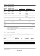
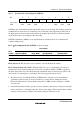
Table 19.1 Operating Modes
CPU Modules
Operating
Mode
Transition
Condition
Clearing
Condition Oscillator Registers Registers I/O Ports
High speed
mode
Control
register
Control
register
Functions High
speed
Function High
speed
Function High speed
Medium-
speed mode
Control
register
Control
register
Functions Medium
speed
Function High/
medium
speed
*
1
Function High speed
Sleep mode Instruction Interrupt Functions Halted Retained High
speed
Function High speed
Module stop
mode
Control
register
Control
register
Functions High/
medium
speed
Function Halted Retained/
reset
*
2
Retained
Software
standby
mode
Instruction External
interrupt
Halted Halted Retained Halted Retained/
reset
*
2
Retained
Hardware
standby
mode
Pin Pin Halted Halted Undefined Halted Reset High
impedance
Notes: 1. The bus master operates on the medium-speed clock, and other on-chip supporting
modules on the high-speed clock.
2. Some SCI registers and the A/D converter are reset, and other on-chip supporting
modules retain their states.
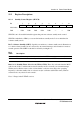
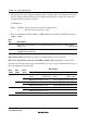
19.1.1 Register Configuration
Power-down modes are controlled by the SBYCR, SCKCR, and MSTPCR registers. Table 19.2
summarizes these registers.
Table 19.2 Power-Down Mode Registers
Name Abbreviation R/W Initial Value Address
*
Standby control register SBYCR R/W H'08 H'FF38
System clock control register SCKCR R/W H'00 H'FF3A
Module stop control register H MSTPCRH R/W H'3F H'FF3C
Module stop control register L MSTPCRL R/W H'FF H'FF3D
Note: * Lower 16 bits of the address.