
Datasheet

Section 18 Clock Pulse Generator
Rev.7.00 Feb. 14, 2007 page 797 of 1108
REJ09B0089-0700
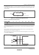
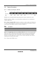
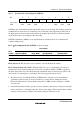
Crystal Resonator: Figure 18.3 shows the equivalent circuit of the crystal resonator. Use a crystal
resonator that has the characteristics shown in table 18.3 and the same resonance frequency as the
system clock (φ).
XTAL
C
L
AT-cut parallel-resonance type
EXTAL
C
0
LR
s
Figure 18.3 Crystal Resonator Equivalent Circuit
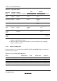
Table 18.3 Crystal Resonator Characteristics
Frequency (MHz) 2 4 8 12 16 20 25
R
S
max (Ω) 500 120 80 60 50 40 40
C
0
max (pF) 7 7 7 7 7 7 7
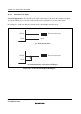
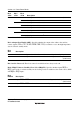
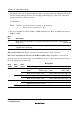
Notes on Board Design: When a crystal resonator is connected, the following points should be
noted:
Other signal lines should be routed away from the oscillator circuit to prevent induction from
interfering with correct oscillation. See figure 18.4.
When designing the board, place the crystal resonator and its load capacitors as close as possible
to the XTAL and EXTAL pins.
C
L2
Signal A Signal B
C
L1
Chip
XTAL
EXTAL
A
void
Figure 18.4 Example of Incorrect Board Design