
Datasheet


Section 17 ROM
Rev.7.00 Feb. 14, 2007 page 602 of 1108
REJ09B0089-0700
17.8 Flash Memory Protection
There are three kinds of flash memory program/erase protection: hardware protection, software
protection, and error protection.
17.8.1 Hardware Protection
Hardware protection refers to a state in which programming/erasing of flash memory is forcibly
disabled or aborted. Settings in flash memory control registers 1 and 2 (FLMCR1, FLMCR2) and
erase block registers 1 and 2 (EBR1, EBR2) are reset (see table 17.11).
Table 17.11 Hardware Protection
Functions
Item Description Program Erase
FWE pin protection
• When a low level is input to the FWE pin,
FLMCR1, FLMCR2, EBR1, and EBR2 are
initialized, and the program/erase-protected
state is entered.
Yes Yes
Reset/standby
protection
• In a reset (including a WDT overflow reset)
and in standby mode, FLMCR1, FLMCR2,
EBR1, and EBR2 are initialized, and the
program/erase-protected state is entered.
• In a reset via the RES pin, the reset state is
not entered unless the RES pin is held low
until oscillation stabilizes after powering on.
In the case of a reset during operation, hold
the RES pin low for the RES pulse width
specified in section 20.3.3, AC
Characteristics.
Yes Yes
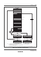
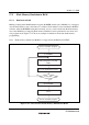
17.8.2 Software Protection
Software protection can be implemented by setting the SWE bit in flash memory control register 1
(FLMCR1), erase block registers 1 and 2 (EBR1, EBR2), and the RAMS bit in the RAM
emulation register (RAMER). When software protection is in effect, setting the P or E bit in
FLMCR1 does not cause a transition to program mode or erase mode (see table 17.12).