
Datasheet


Section 13 Smart Card Interface
Rev.7.00 Feb. 14, 2007 page 525 of 1108
REJ09B0089-0700
13.3.7 Operation in GSM Mode
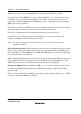
Switching the Mode: When switching between smart card interface mode and software standby
mode, the following switching procedure should be followed in order to maintain the clock duty.
• When changing from smart card interface mode to software standby mode
[1] Set the data register (DR) and data direction register (DDR) corresponding to the SCK pin to
the value for the fixed output state in software standby mode.
[2] Write 0 to the TE bit and RE bit in the serial control register (SCR) to halt the transmit/receive
operation. At the same time, set the CKE1 bit to the value for the fixed output state in
software standby mode.
[3] Write 0 to the CKE0 bit in SCR to halt the clock.
[4] Wait for one serial clock period.
During this interval, clock output is fixed at the specified level, with the duty preserved.
[5] Write H'00 to SMR and SCMR.
[6] Make the transition to the software standby state.
• When returning to smart card interface mode from software standby mode
[7] Exit the software standby state.
[8] Set the CKE1 bit in SCR to the value for the fixed output state (current SCK pin state) when
software standby mode is initiated.
[9] Set smart card interface mode and output the clock. Signal generation is started with the
normal duty.
[1] [2] [3] [4] [5] [6] [7] [8] [9]
Software
standby
Normal operation Normal operation
Figure 13.9 Clock Halt and Restart Procedure