
Datasheet


Section 13 Smart Card Interface
Rev.7.00 Feb. 14, 2007 page 520 of 1108
REJ09B0089-0700
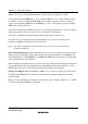
(1) Data write
TDR
TSR
(shift register)
Data 1
(2) Transfer from
TDR to TSR
Data 1 Data 1 ; Data remains in TDR
(3) Serial data output
Note: When the ERS flag is set, it should be cleared until transfer of the last bit (D7 in LSB-first
transmission, D0 in MSB-first transmission) of the next transfer data to be transmitted has
been completed.
In case of normal transmission: TEND flag is set
In case of transmit error: ERS flag is set
Steps (2) and (3) above are repeated until the TEND flag is set
I/O signal line output
Data 1
Data 1
Figure 13.5 Relation Between Transmit Operation and Internal Registers
Ds D0 D1 D2 D3 D4 D5 D6 D7 DpI/O data
12.5 etu
TXI
(TEND interrupt)
Note: etu: Elementary time unit (time for transfer of 1 bit)
11.0 etu
DE
Guard
time
When GM = 1
Legend:
Ds: Start bit
D0 to D7: Data bits
Dp: Parity bit
DE: Error signal
When GM = 0
Figure 13.6 TEND Flag Generation Timing in Transmission