
Datasheet


Section 8 I/O Ports
Rev.7.00 Feb. 14, 2007 page 254 of 1108
REJ09B0089-0700
8.6.2 Register Configuration
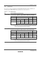
Table 8.9 shows the port A register configuration.
Table 8.9 Port A Registers
Name Abbreviation R/W Initial Value
*
1
Address
*
2
Port A data direction register PADDR W H'0 H'FEB9
Port A data register PADR R/W H'0 H'FF69
Port A register PORTA R Undefined H'FF59
Port A MOS pull-up control register PAPCR R/W H'0 H'FF70
Port A open-drain control register PAODR R/W H'0 H'FF77
Notes: 1. Value of bits 3 to 0.
2. Lower 16 bits of the address.
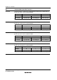
Port A Data Direction Register (PADDR)
Bit : 7 6 5 4 3 2 1 0
— — — — PA3DDR PA2DDR PA1DDR PA0DDR
Initial value : Undefined Undefined Undefined Undefined 0 0 0 0
R/W : — — — — W W W W
PADDR is an 8-bit write-only register, the individual bits of which specify input or output for the
pins of port A. PADDR cannot be read; if it is, an undefined value will be read. Bits 7 to 4 are
reserved.
PADDR is initialized to H'0 (bits 3 to 0) by a reset and in hardware standby mode. It retains its
prior state in software standby mode. The OPE bit in SBYCR is used to select whether the address
output pins retain their output state or become high-impedance when a transition is made to
software standby mode.
• Modes 4 and 5
The corresponding port A pins are address outputs irrespective of the value of bits PA3DDR to
PA0DDR.
• Mode 6
*
Setting PADDR bits to 1 makes the corresponding port A pins address outputs, while clearing
the bits to 0 makes the pins input ports.