
Datasheet


Section 6 Bus Controller
Rev.7.00 Feb. 14, 2007 page 161 of 1108
REJ09B0089-0700
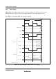
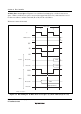
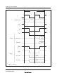
8-Bit 3-State Access Space: Figure 6.7 shows the bus timing for an 8-bit 3-state access space.
When an 8-bit access space is accessed, the upper half (D
15
to D
8
) of the data bus is used.
The LWR pin is fixed high. Wait states can be inserted.
Bus cycle
T
1
T
2
Address bus
φ
CSn
AS
RD
D
15
to D
8
Valid
D
7
to D
0
Invalid
Read
HWR
LWR
D
15
to D
8
Valid
D
7
to D
0
High impedance
Write
High
Note: n = 0 to 7
T
3
Figure 6.7 Bus Timing for 8-Bit 3-State Access Space