
Datasheet


Rev.7.00 Feb. 14, 2007 page x of xxxii
REJ09B0089-0700
Item Page Revision (See Manual for Details)
17.8.3 Error
Protection
604 Description amended
(Before) • When a bus master other than the CPU (the DMAC
or DTC) has control ... → (After) • When a bus master other
than the CPU (the DTC) has control ...
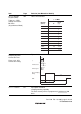
17.11.2 Socket
Adapters and Memory
Map
609 Description added
In programmer mode, ... figure 17.21. This enables the chip to
fit a 40-pin socket. Figure 17.20 shows ...
17.13.1 Features 629 Description amended
• Reprogramming capability
The flash memory can be reprogrammed a minimum of 100
times.
17.17.3 Error
Protection
664 Description amended
(Before) • When a bus master other than the CPU (the DMAC
or DTC) has control ... → (After) • When a bus master other
than the CPU (the DTC) has control ...
17.20.2 Socket
Adapters and Memory
Map
670 Description added
In programmer mode, ... figure 17.51. This enables the chip to
fit a 40-pin socket. Figure 17.50 shows ...
17.22.1 Features 686 Description amended
• Protection modes
There are three protection modes: software protection by the
register setting, hardware protection by reset/hardware standby,
and error protection. The protection ...
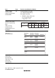
17.22.4 Mode
Comparison
Table 17.46
Comparison of
Programming Modes
690 Table 17.46 amended
Boot mode
User program
mode User boot mode PROM mode
Programming/
Erasing
Environment
On-board
programming
On-board
programming
On-board
programming
On-board
programmi
ng
Programming/
Erasing Enable
MAT
User MAT
User boot MAT
User MAT User MAT User MAT
User boot MA
T
Program/Erase
Control
Command method Programming/
Erasing Interface
Programming/
Erasing Interface
Command method
All Erasure
(Automatic) (Automatic)
17.23.2
Programming/Erasing
Interface Parameter
704 Description amended
... the CPU except for ER0 and ER1 are stored. The return
value of ... the registers except for ER0 and ER1, the stack area
must be ...