
Datasheet


Section 12 8-Bit Timers
Rev. 6.00 Mar. 18, 2010 Page 443 of 982
REJ09B0054-0600
12.2 Input/Output Pins
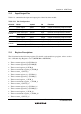
Table 12.1 summarizes the input and output pins of the 8-bit timer module.
Table 12.1 Pin Configuration
Channel Name Symbol I/O Function
0 Timer output TMO0 Output Output controlled by compare-match
1 Timer output TMO1 Output Output controlled by compare-match
Timer clock input TMCI01 Input External clock input for the counter Common to
0 and 1
Timer reset input TMRI01 Input External reset input for the counter
2 Timer output TMO2
*
Output Output controlled by compare-match
3 Timer output TMO3
*
Output Output controlled by compare-match
Timer clock input TMCI23
*
Input External clock input for the counter Common to
2 and 3
Timer reset input TMRI23
*
Input External reset input for the counter
Note: * Not available in the H8S/2237 Group and H8S/2227 Group.
12.3 Register Descriptions
The 8-bit timer has the following registers. For details on the module stop register, refer to section
24.1.2, Module Stop Registers A to C (MSTPCRA to MSTPCRC).
• Time constant register A_0 (TCORA_0)
• Time constant register B_0 (TCORB_0)
• Timer control register_0 (TCR_0)
• Timer control/status register_0 (TCSR_0)
• Timer counter_1 (TCNT_1)
• Time constant register A_1 (TCORA_1)
• Time constant register B_1 (TCORB_1)
• Timer control register_1 (TCR_1)
• Timer control/status register_1 (TCSR_1)
• Timer counter_2 (TCNT_2)*
• Time constant register A_2 (TCORA_2)*
• Time constant register B_2 (TCORB_2)*
• Timer control register_2 (TCR_2)*
• Timer control/status register_2 (TCSR_2)*
• Timer counter_3 (TCNT_3)*