
Datasheet


Section 7 Bus Controller
Rev. 6.00 Mar. 18, 2010 Page 191 of 982
REJ09B0054-0600
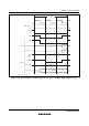
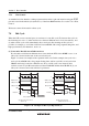
(2) Pin Wait Insertion
Setting the WAITE bit in BCRL to 1 enables wait insertion by means of the WAIT pin. When
external space is accessed in this state, program wait insertion is first carried out according to
the settings in WCRH and WCRL. Then, if the WAIT pin is low at the falling edge of φ in the
last T
2
or T
W
state, a T
W
state is inserted. If the WAIT pin is held low, T
W
states are inserted
until it goes high.
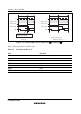
Figure 7.18 shows an example of wait state insertion timing.
By program
wait
T
1
Address bus
φ
AS
RD
Data bus
Read data
Read
HWR, LWR
Write data
Write
Note: ↓ indicates the timing of WAIT pin sampling.
WAIT
Data bus
T
2
T
w
T
w
T
w
T
3
By WAIT pin
Figure 7.18 Example of Wait State Insertion Timing