
Datasheet


Section 12 8-Bit Timers
Rev. 6.00 Mar. 18, 2010 Page 452 of 982
REJ09B0054-0600
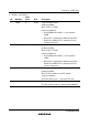
Bit Bit Name
Initial
Value
R/W Description
3
2
OS3
OS2
0
0
R/W
R/W
Output Select 3 and 2
These bits specify how the timer output level is to be
changed by a compare-match B of TCORB and
TCNT.
00: No change when compare-match B occurs
01: 0 is output when compare-match B occurs
10: 1 is output when compare-match B occurs
11: Output is inverted when compare-match B occurs
(toggle output)
1
0
OS1
OS0
0
0
R/W
R/W
Output Select 1 and 0
These bits specify how the timer output level is to be
changed by a compare-match A of TCORA and
TCNT.
00: No change when compare-match A occurs
01: 0 is output when compare-match A occurs
10: 1 is output when compare-match A occurs
11: Output is inverted when compare-match A occurs
(toggle output)
Notes: 1. Not available in the H8S/2237 Group and H8S/2227 Group.
2. Only 0 can be written to this bit, to clear the flag.
12.4 Operation
12.4.1 Pulse Output
Figure 12.2 shows an example of arbitrary duty pulse output.
1. Set TCR in CCR1 to 0 and CCLR0 to 1 to clear TCNT by a TCORA compare-match.
2. Set OS3 to OS0 bits in TCSR to B'0110 to output 1 by a compare-match A and 0 by compare-
match B.
By the above settings, waveforms with the cycle of TCORA and the pulse width of TCRB can be
output without software intervention.