
User manual


Table Of Contents
- Notes regarding these materials
- Precautions on Using The Product Described Herein
- For Inquiries About Product Contents or This Manual
- Preface
- Contents
- 1. Overview
- 2. Contents of the Product Package
- 3. Usage Precautions
- 4. Starter Kit Usage Conditions
- 5. Hardware Setup
- 6. Software Setup
- Appendix 1 Contents of CD-ROM
- Appendix 2 Part List
- Appendix 3 M3A-2152G02 Product Standards
- 1. Overview
- 2. Functional Specifications
- 2.1 Configuration of the Power Supply
- 2.2 FP Select Circuit
- 2.3 MOD Select Circuit
- 2.4 Serial I/O Interface
- 2.5 Oscillator Circuit
- 2.6 General-purpose Output Port LED Indicators
- 2.7 General-purpose Input Port Control Circuit
- 2.8 Analog Port Input Control Circuit
- 2.9 CAN Interface
- 2.10 JTAG Peripheral Circuit
- 3. Reference Data
- REVISION HISTORY
32176 Group
Starter Kit User’s Manual M3A-2152
REJ10B0224-0300/Rev.3.00 Jan. 2007 Page 3 of 82
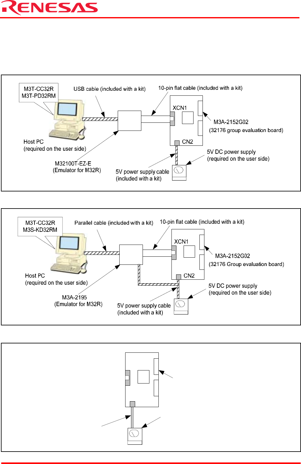
1.2 System Configuration
Figure 1.1, Figure 1.2 and Figure 1.3 below show system configurations of M3A-2152G52A
connected to an included emulator, system configurations of M3A-2152G52 connected to an
included emulator and M3A-2152G02 by itself, respectively.
Figure 1.1 System Configuration of M3A-2152G52A Connected to an Included Emulator
Figure 1.2 System Configuration of M3A-2152G52A Connected to an Included Emulator
Figure 1.3 System Configuration of M3A-2154G02A by Itself
M3A-2152G02
(32176 Group evaluation board)
5V power supply cable
(included with a kit)
CN2
XCN1
5V DC power supply
(required on the user side)