
User manual


Table Of Contents
- Notes regarding these materials
- Precautions on Using The Product Described Herein
- For Inquiries About Product Contents or This Manual
- Preface
- Contents
- 1. Overview
- 2. Contents of the Product Package
- 3. Usage Precautions
- 4. Starter Kit Usage Conditions
- 5. Hardware Setup
- 6. Software Setup
- Appendix 1 Contents of CD-ROM
- Appendix 2 Part List
- Appendix 3 M3A-2152G02 Product Standards
- 1. Overview
- 2. Functional Specifications
- 2.1 Configuration of the Power Supply
- 2.2 FP Select Circuit
- 2.3 MOD Select Circuit
- 2.4 Serial I/O Interface
- 2.5 Oscillator Circuit
- 2.6 General-purpose Output Port LED Indicators
- 2.7 General-purpose Input Port Control Circuit
- 2.8 Analog Port Input Control Circuit
- 2.9 CAN Interface
- 2.10 JTAG Peripheral Circuit
- 3. Reference Data
- REVISION HISTORY
.
o
N GNI
W
AR
D
G
P
ETAD MET
I
NO
I
TPI
R
C
S
E
D
)
LA
IRETAM
(
R
EB
MUN LAIRETAM
E
MULOV
63403KD
10G2512-A3M
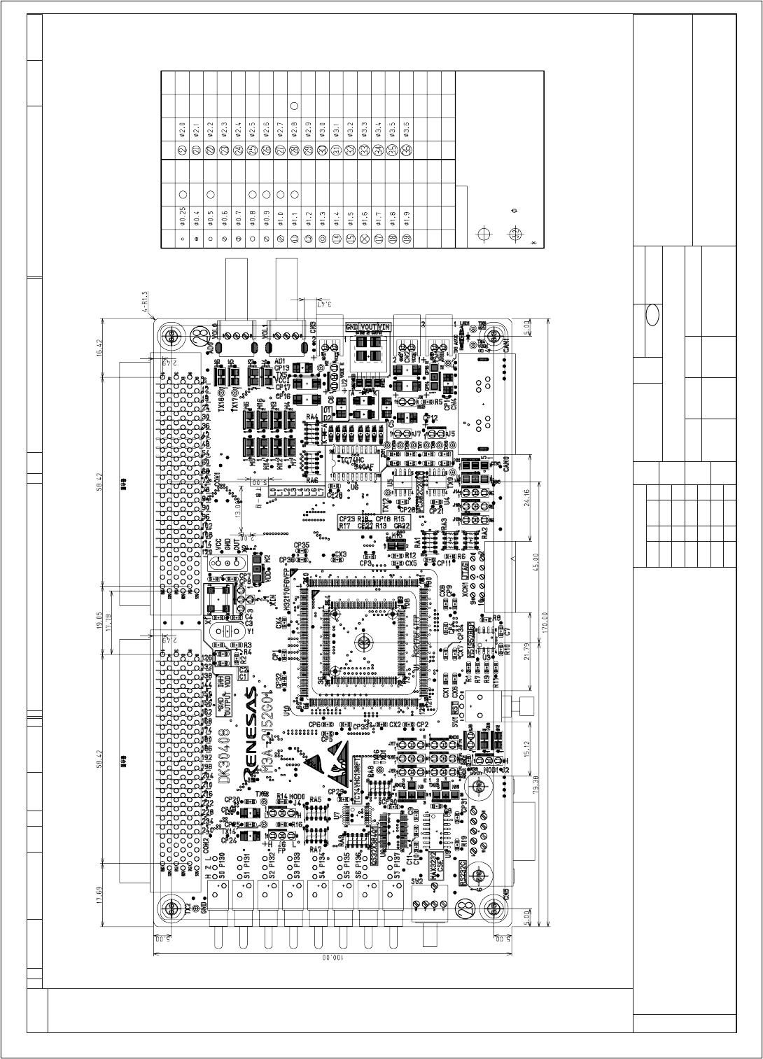
noisnemid lanretxe fo margaiD
)1/1(
NOITAROPROC YGOLONHCET SASENER
ELGNA DR3
N
OI
T
CEJ
O
RP
5-3-30
STN
/
E
T
A
D
ELA
CS
M
ID
NI
mm
DEVO
R
PPA
NGISEDN
W
ARD DEK
C
EHC
mm:NOISNEMID
CHANGE
Detail table of Through-Hole
Hole
Symbol
Hole
Diameter
Occupancy
Remarks
Hole
Symbol
Hole
Diameter
Occupancy
Remarks
Mounting hole details
[Example]
shows the hole symbol of the mounting hole.
is 3.2 mounting hole.
Hole Diameter shows the finished diameter of each hole.
REJ10B0224-0300/Rev.3.00 Jan. 2007 Page 81 of 82