
User manual


Table Of Contents
- Notes regarding these materials
- Precautions on Using The Product Described Herein
- For Inquiries About Product Contents or This Manual
- Preface
- Contents
- 1. Overview
- 2. Contents of the Product Package
- 3. Usage Precautions
- 4. Starter Kit Usage Conditions
- 5. Hardware Setup
- 6. Software Setup
- Appendix 1 Contents of CD-ROM
- Appendix 2 Part List
- Appendix 3 M3A-2152G02 Product Standards
- 1. Overview
- 2. Functional Specifications
- 2.1 Configuration of the Power Supply
- 2.2 FP Select Circuit
- 2.3 MOD Select Circuit
- 2.4 Serial I/O Interface
- 2.5 Oscillator Circuit
- 2.6 General-purpose Output Port LED Indicators
- 2.7 General-purpose Input Port Control Circuit
- 2.8 Analog Port Input Control Circuit
- 2.9 CAN Interface
- 2.10 JTAG Peripheral Circuit
- 3. Reference Data
- REVISION HISTORY
32176 Group
Starter Kit User’s Manual M3A-2152
REJ10B0224-0300/Rev.3.00 Jan. 2007 Page 60 of 82
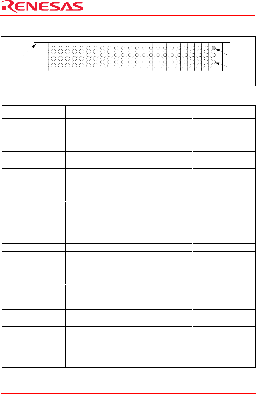
3.2.2 Pin Assignments of the Extension Connector CON2
Figure 3.2 CON2 Connector Pin Assignments (View from Side of Mounted Items)
Table 3.4 CON2 Connector Pin Assignments
Pin No.
Signal
Name
Pin No.
Signal
Name
Pin No.
Signal
Name
Pin No.
Signal
Name
1 (121) P96 31 (151) NC 61 (181) P174 91 (211) P1
2 (122) P95 32 (152) NC 62 (182) P175 92 (212) P0
3 (123) P94 33 (153) NC 63 (183) NC 93 (213) GND
4 (124) P93 34 (154) VCCE 64 (184) NC 94 (214) P73
5 (125) VCCE 35 (155) GND 65 (185) NC 95 (215) P72
6 (126) GND 36 (156) NC 66 (186) NC 96 (216) P71
7 (127) NC 37 (157) NC 67 (187) FP 97 (217) P70
8 (128) P27 38 (158) NC 68 (188) MOD0 98 (218) P43
9 (129) P26 39 (159) NC 69 (189) NC 99 (219) P42
10 (130) P25 40 (160) NC 70 (190) NC 100 (220) P41
11 (131) P24 41 (161) NC 71 (191) GND 101 (221) NC
12 (132) P23 42 (162) NC 72 (192) NC 102 (222) GND
13 (133) P22 43 (163) NC 73 (193) NC 103 (223) NC
14 (134) P21 44 (164) NC 74 (194) GND 104 (224) NC
15 (135) P20 45 (165) NC 75 (195) VCCE 105 (225) NC
16 (136) GND 46 (166) NC 76 (196) NC 106 (226) NC
17 (137) P37 47 (167) NC 77 (197) P17 107 (227) NC
18 (138) P36 48 (168) NC 78 (198) P16 108 (228) NC
19 (139) P35 49 (169) NC 79 (199) P15 109 (229) NC
20 (140) P34 50 (170) NC 80 (200) P14 110 (230) NC
21 (141) P33 51 (171) NC 81 (201) P13 111 (231) GND
22 (142) P32 52 (172) NC 82 (202) P12 112 (232) NC
23 (143) P31 53 (173) NC 83 (203) P11 113 (233) NC
24 (144) P30 54 (174) NC 84 (204) P10 114 (234) NC
25 (145) P47 55 (175) P87 85 (205) P7 115 (235) NC
26 (146) P46 56 (176) P86 86 (206) P6 116 (236) NC
27 (147) P225 57 (177) P85 87 (207) P5 117 (237) NC
28 (148) NC 58 (178) P84 88 (208) P4 118 (238) NC
29 (149) P45 59 (179) P83 89 (209) P3 119 (239) NC
30 (150) P44 60 (180) P82 90 (210) P2 120 (240) NC
Note: NC denotes “Not Connected.”
Board edge
CON2
1st pin
3rd pin
126198 186 174 162 150 138234 222 210
132204 192 180 168 156 144240 228 216