
User manual


Table Of Contents
- Notes regarding these materials
- Precautions on Using The Product Described Herein
- For Inquiries About Product Contents or This Manual
- Preface
- Contents
- 1. Overview
- 2. Contents of the Product Package
- 3. Usage Precautions
- 4. Starter Kit Usage Conditions
- 5. Hardware Setup
- 6. Software Setup
- Appendix 1 Contents of CD-ROM
- Appendix 2 Part List
- Appendix 3 M3A-2152G02 Product Standards
- 1. Overview
- 2. Functional Specifications
- 2.1 Configuration of the Power Supply
- 2.2 FP Select Circuit
- 2.3 MOD Select Circuit
- 2.4 Serial I/O Interface
- 2.5 Oscillator Circuit
- 2.6 General-purpose Output Port LED Indicators
- 2.7 General-purpose Input Port Control Circuit
- 2.8 Analog Port Input Control Circuit
- 2.9 CAN Interface
- 2.10 JTAG Peripheral Circuit
- 3. Reference Data
- REVISION HISTORY
32176 Group
Starter Kit User’s Manual M3A-2152
REJ10B0224-0300/Rev.3.00 Jan. 2007 Page 57 of 82
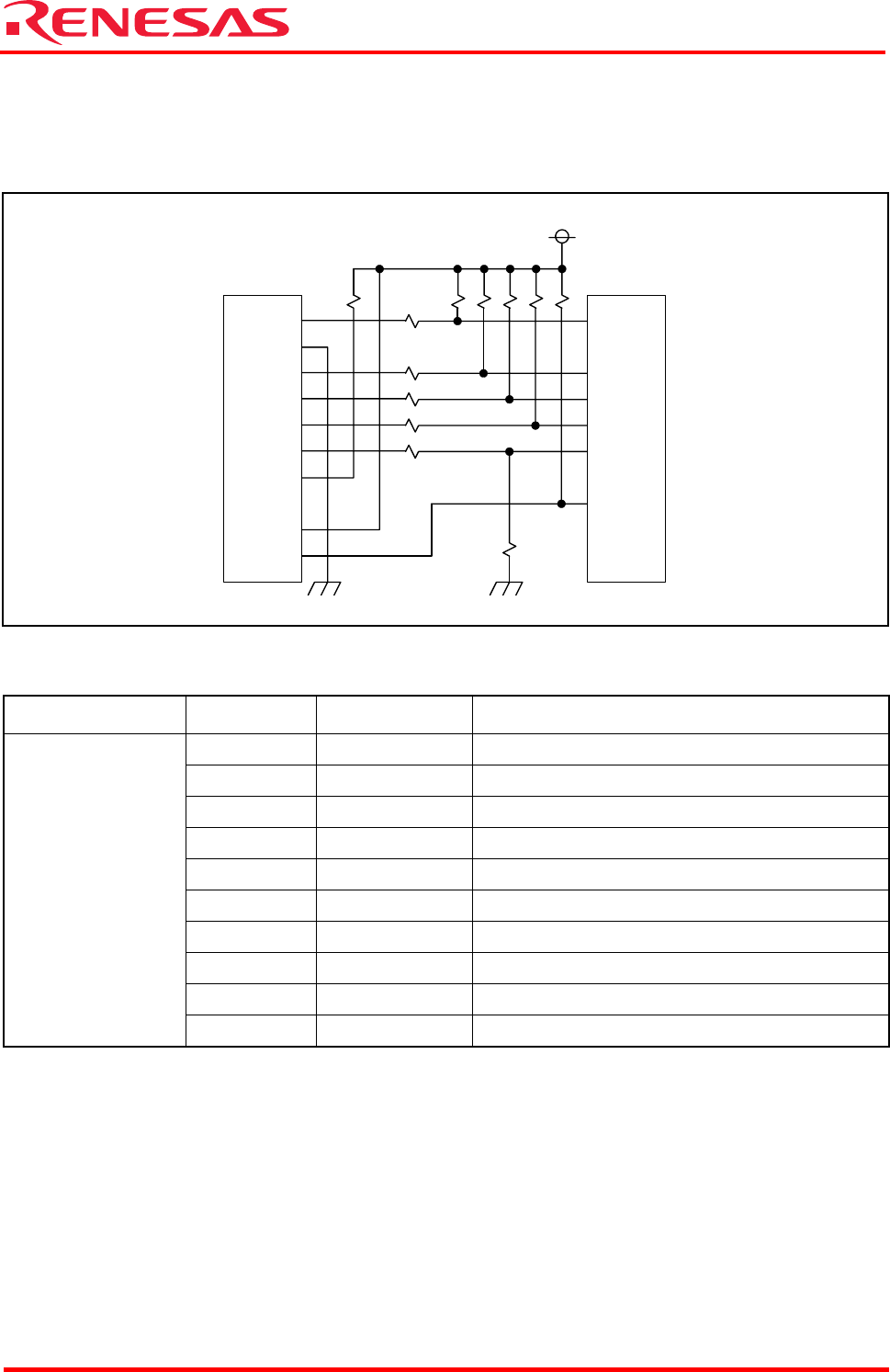
2.10 JTAG Peripheral Circuit
The evaluation board comes standard with a connector for Renesas SDI. This connector consists of
the 2.54-mm contact pitch XG4C-1034 made by Omron Corporation.
Figure 2.11 JTAG/NBD Interface
Table 2.16 JTAG Connector Pin Assignments
Connector Name Pin No Signal Name Description
1 JTCK Test clock
2 GND Ground
3 JTDI Test data input
4 JTDO Test data output
5 JTMS Test mode select
6 JTRST Test reset
7 JDBI Break request
8 VCC Power supply
9 JVCC User system power supply monitor
XCN1
10 RESET Reset
XCN1
VCC
1
U1
M32R/ECU
JTCK
JTDI
JTDO
JTMS
JTRST
RESET
10
9
8
7
6
5
4
3
2