
User manual


Table Of Contents
- Notes regarding these materials
- Precautions on Using The Product Described Herein
- For Inquiries About Product Contents or This Manual
- Preface
- Contents
- 1. Overview
- 2. Contents of the Product Package
- 3. Usage Precautions
- 4. Starter Kit Usage Conditions
- 5. Hardware Setup
- 6. Software Setup
- Appendix 1 Contents of CD-ROM
- Appendix 2 Part List
- Appendix 3 M3A-2152G02 Product Standards
- 1. Overview
- 2. Functional Specifications
- 2.1 Configuration of the Power Supply
- 2.2 FP Select Circuit
- 2.3 MOD Select Circuit
- 2.4 Serial I/O Interface
- 2.5 Oscillator Circuit
- 2.6 General-purpose Output Port LED Indicators
- 2.7 General-purpose Input Port Control Circuit
- 2.8 Analog Port Input Control Circuit
- 2.9 CAN Interface
- 2.10 JTAG Peripheral Circuit
- 3. Reference Data
- REVISION HISTORY
32176 Group
Starter Kit User’s Manual M3A-2152
REJ10B0224-0300/Rev.3.00 Jan. 2007 Page 45 of 82
1.4 Specifications of the Evaluation Board
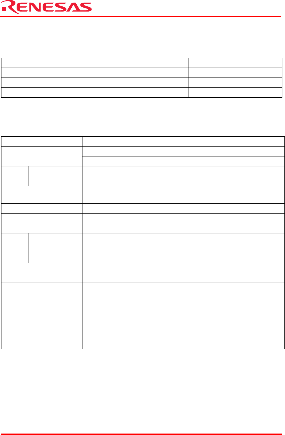
1.4.1 Electrical Characteristics
Table 1.3 Electrical Characteristics
Symbol Parameter Rated Value
VCCE, AVCC Power supply voltage 4.75 V to 5.25 V
Tstr Storage ambient temperature 0°C to 70°C
Topr Operating ambient temperature 0°C to 70°C
Note: Operating conditions require that no dewdrops and corrosive gas be present.
1.4.2 Functional Characteristics
Table 1.4 Functional Characteristics
Item M3A-2152G02
M32176F4VFP(U1)
CPU
Clock input: 10 MHz; CPU clock: 40 MHz
Flash memory 512 KB
Memory
SRAM 24 KB
RS-232C interface
Comes standard with a 9-pin Dsub connector (CN5) for serial
communication with the host PC (DOS/V)
JTAG interface Comes standard with an SDI connector (XCN1)
CAN interface
Comes standard with a 2-channel connector for CAN communication (CN4),
a CAN-to-Dsub connector (9-pin) conversion cord included
VCCE Power supply, Connector (CN2)
AVCC Analog circuit power supply, Connector (CN1)
Power
supply
LED Illuminates in red when powered on (LED1)
General-purpose output LED indicators (L0–L7), CPU ports (P110–P117)
General-purpose input Toggle switches (S0–S7), CPU ports (P130–P137)
Reset
Reset switch (SW1), reset input (red pushbutton)
*Please be careful to configure a reset circuit according to your
system.
Serial I/O Rotary switch (SW2), which selects one of four serial I/O channels
Analog input
VR controls (VOL0, VOL1)
Connects these VR controls with AD0IN0 and AD0IN1 to use them to
control inputs on ports
Extension Extension connectors (CON1, CON2)