
User manual


Table Of Contents
- Notes regarding these materials
- Precautions on Using The Product Described Herein
- For Inquiries About Product Contents or This Manual
- Preface
- Contents
- 1. Overview
- 2. Contents of the Product Package
- 3. Usage Precautions
- 4. Starter Kit Usage Conditions
- 5. Hardware Setup
- 6. Software Setup
- Appendix 1 Contents of CD-ROM
- Appendix 2 Part List
- Appendix 3 M3A-2152G02 Product Standards
- 1. Overview
- 2. Functional Specifications
- 2.1 Configuration of the Power Supply
- 2.2 FP Select Circuit
- 2.3 MOD Select Circuit
- 2.4 Serial I/O Interface
- 2.5 Oscillator Circuit
- 2.6 General-purpose Output Port LED Indicators
- 2.7 General-purpose Input Port Control Circuit
- 2.8 Analog Port Input Control Circuit
- 2.9 CAN Interface
- 2.10 JTAG Peripheral Circuit
- 3. Reference Data
- REVISION HISTORY
32176 Group
Starter Kit User’s Manual M3A-2152
REJ10B0224-0300/Rev.3.00 Jan. 2007 Page 44 of 82
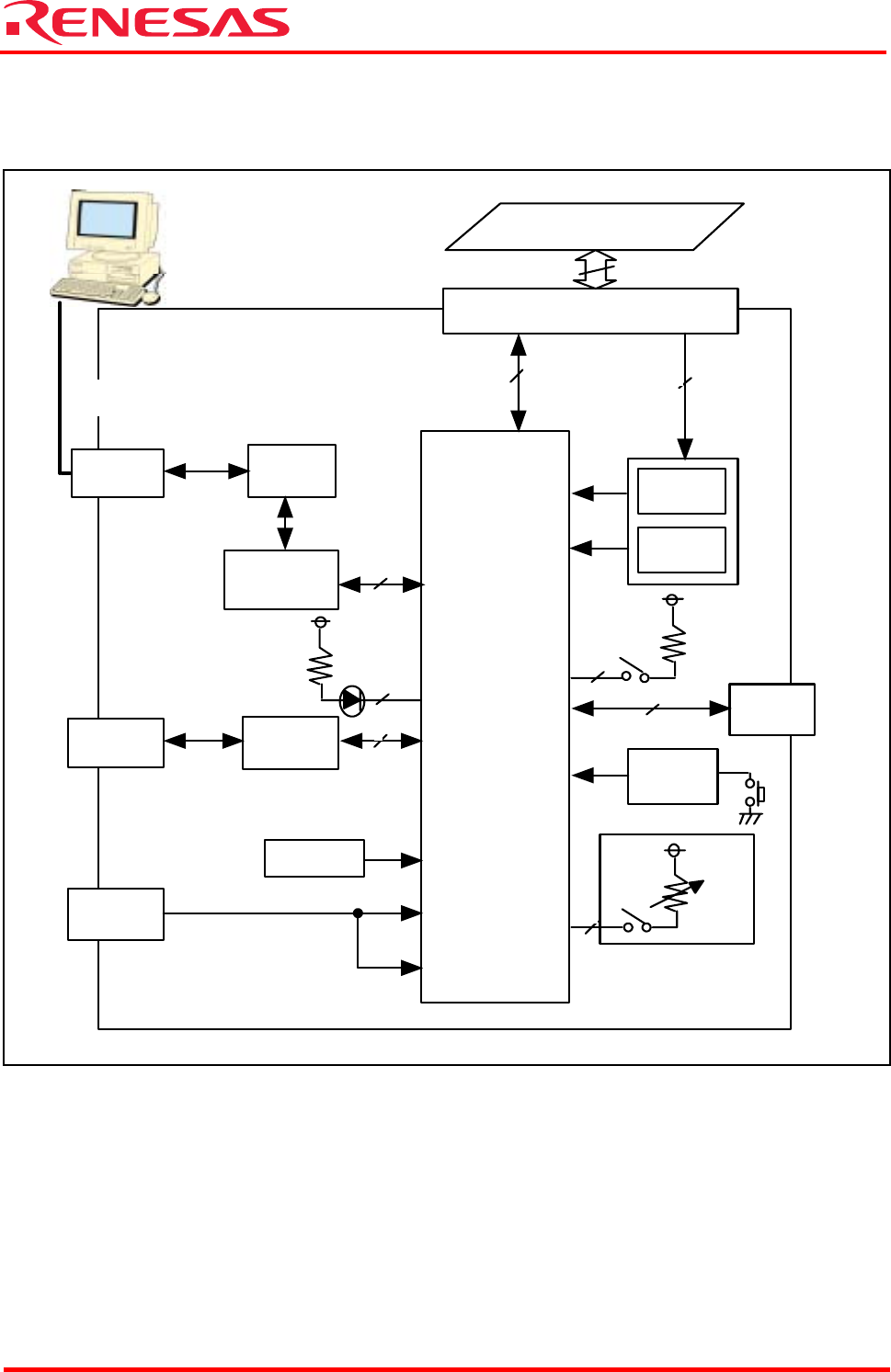
1.3 Block Diagram
A block diagram of the M3A-2152G02 is shown below.
Figure 1.3 Block Diagram of the M3A-2154G02A
RS-232C
connector
RS-232C
driver
CAN
connector
CAN
driver
SIO
CAN
FP select
MOD
select
MOD0/
MOD1
FP
VCCE
power supply
connector
VCCE
AVCC/VDDE
Extension connector
Port
JTAG
connector
Reset
circuit
JTAG
RESET
AD
Oscillator
circuit
XIN
RS-232C
cable
Host machine
(DOS/V)
Extension board
Serial I/O
channel select
M32176F4VFP
2
4
8
144
144
5
8
PORT13
PORT11
8
2
(JTAG, MCU control and
other pins excluded)
(JTAG, MCU control and
other pins excluded)