
User manual


Table Of Contents
- Notes regarding these materials
- Precautions on Using The Product Described Herein
- For Inquiries About Product Contents or This Manual
- Preface
- Contents
- 1. Overview
- 2. Contents of the Product Package
- 3. Usage Precautions
- 4. Starter Kit Usage Conditions
- 5. Hardware Setup
- 6. Software Setup
- Appendix 1 Contents of CD-ROM
- Appendix 2 Part List
- Appendix 3 M3A-2152G02 Product Standards
- 1. Overview
- 2. Functional Specifications
- 2.1 Configuration of the Power Supply
- 2.2 FP Select Circuit
- 2.3 MOD Select Circuit
- 2.4 Serial I/O Interface
- 2.5 Oscillator Circuit
- 2.6 General-purpose Output Port LED Indicators
- 2.7 General-purpose Input Port Control Circuit
- 2.8 Analog Port Input Control Circuit
- 2.9 CAN Interface
- 2.10 JTAG Peripheral Circuit
- 3. Reference Data
- REVISION HISTORY
32176 Group
Starter Kit User’s Manual M3A-2152
REJ10B0224-0300/Rev.3.00 Jan. 2007 Page 42 of 82
1. Overview
1.1 Outline of the Product
Table 1.1 Mounted Microcomputer Type
Mounted microcomputer type name M32176F4VFP
Evaluation board type name (socket mounted type) M3A-2152G02
Table 1.2 Specification of Product
Operation mode Single-chip mode, Processor mode and External extension mode
Board extension Can be extended using the board’s extension connector
CAN I/F Comes standard with a 2-channel CAN connector, CAN modular cord included
RS-232C I/F Comes standard with an RS-232C connector
Serial port One of four channels can be selected using a rotary switch
Analog port Inputs on two channels can be controlled using variable resistor (VR) controls
Display I/O Comes with a single-port LED
Input I/O Comes with a single-port toggle switch
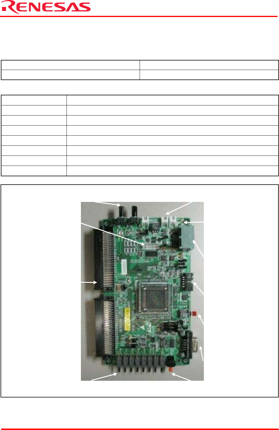
Figure 1.1 Photograph of the M3A-2152G02
Power supply connector
CAN connector
Reset key
JTAG connector
RS-232C connector
Rotary switch
(selects a serial I/O channel)
Toggle switch
(port input)
LED indicator
(port output)
VR controls
External
extension
connector
LED indicator
(power-on)