
User manual


Table Of Contents
- Notes regarding these materials
- Precautions on Using The Product Described Herein
- For Inquiries About Product Contents or This Manual
- Preface
- Contents
- 1. Overview
- 2. Contents of the Product Package
- 3. Usage Precautions
- 4. Starter Kit Usage Conditions
- 5. Hardware Setup
- 6. Software Setup
- Appendix 1 Contents of CD-ROM
- Appendix 2 Part List
- Appendix 3 M3A-2152G02 Product Standards
- 1. Overview
- 2. Functional Specifications
- 2.1 Configuration of the Power Supply
- 2.2 FP Select Circuit
- 2.3 MOD Select Circuit
- 2.4 Serial I/O Interface
- 2.5 Oscillator Circuit
- 2.6 General-purpose Output Port LED Indicators
- 2.7 General-purpose Input Port Control Circuit
- 2.8 Analog Port Input Control Circuit
- 2.9 CAN Interface
- 2.10 JTAG Peripheral Circuit
- 3. Reference Data
- REVISION HISTORY
Handling
Classification
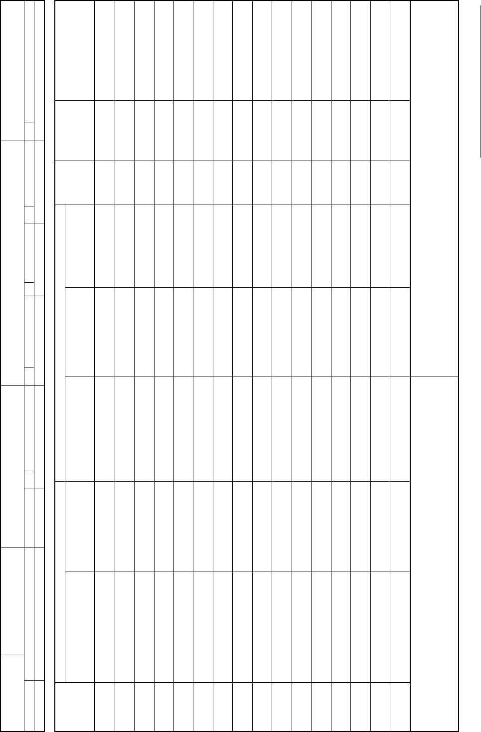
Part List
No.
PPL-M3A-2152G52A
Title
M3A-2152G52A
Division in charge
Created Revision
Checked
Part Name Part Specification
Item No.
Description Part No.
Part Type Name
(Drawing No.,Product
Specification)
Manufacturer Name
Mounting
Direction
Required
Q’ty per
Unit
Supply
Classification
Remarks
1
M32R/ECU#4NL
Evaluation board
PLL-M3A-2152G02 M3A-2152G02
1
2
Emulator for 32176
Group MCU
M32100T-EZ-E
1
3 USB cable
1
4 10-pin flat cable
1
5 CD-ROM
1
6
IMPORTANT-READ ME
FIRST
1
7
M32R/ECU Starter kit
Release note
1
*
Special note:
(1) Blank columns denote the same content as the upper row.
(2) If two or more part type names are written for one part, the upper row has priority.
(3) The asterisk (*) in the item No. column denotes that the rest is blank.
Special note:
PLL-M3A-2152G52A ( 1 / 1 )
REJ10B0224-0300/Rev.3.00 Jan. 2007 Page 39 of 82