
User manual


Table Of Contents
- Notes regarding these materials
- Precautions on Using The Product Described Herein
- For Inquiries About Product Contents or This Manual
- Preface
- Contents
- 1. Overview
- 2. Contents of the Product Package
- 3. Usage Precautions
- 4. Starter Kit Usage Conditions
- 5. Hardware Setup
- 6. Software Setup
- Appendix 1 Contents of CD-ROM
- Appendix 2 Part List
- Appendix 3 M3A-2152G02 Product Standards
- 1. Overview
- 2. Functional Specifications
- 2.1 Configuration of the Power Supply
- 2.2 FP Select Circuit
- 2.3 MOD Select Circuit
- 2.4 Serial I/O Interface
- 2.5 Oscillator Circuit
- 2.6 General-purpose Output Port LED Indicators
- 2.7 General-purpose Input Port Control Circuit
- 2.8 Analog Port Input Control Circuit
- 2.9 CAN Interface
- 2.10 JTAG Peripheral Circuit
- 3. Reference Data
- REVISION HISTORY
32176 Group
Starter Kit User’s Manual M3A-2152
REJ10B0224-0300/Rev.3.00 Jan. 2007 Page 23 of 82
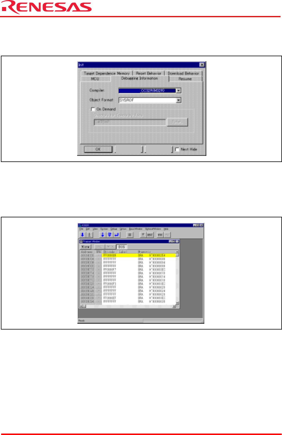
Selecting a Cross Tool
While the Debugging Information tab is open, select “CC32R(M32R)” for Compiler.
For the Starter Kit, M3T-CC32R is the only cross tool which has had its operation guaranteed.
Figure 6.9 Selecting a Cross Tool
When you have finished the above initialization, click the “OK” button to start M3S-KD32R.
If M3S-KD32R communicates normally with the target system, it starts up and the M3S-KD32R
window shown in Figure 6.10 appears. For details on how to use it, refer to the M3S-KD32R
Release Note and the PD32R Help.
Figure 6.10 M3S-KD32R Window at Normal Startup
Cancel Hel
p