
User manual


Table Of Contents
- Notes regarding these materials
- Precautions on Using The Product Described Herein
- For Inquiries About Product Contents or This Manual
- Preface
- Contents
- 1. Overview
- 2. Contents of the Product Package
- 3. Usage Precautions
- 4. Starter Kit Usage Conditions
- 5. Hardware Setup
- 6. Software Setup
- Appendix 1 Contents of CD-ROM
- Appendix 2 Part List
- Appendix 3 M3A-2152G02 Product Standards
- 1. Overview
- 2. Functional Specifications
- 2.1 Configuration of the Power Supply
- 2.2 FP Select Circuit
- 2.3 MOD Select Circuit
- 2.4 Serial I/O Interface
- 2.5 Oscillator Circuit
- 2.6 General-purpose Output Port LED Indicators
- 2.7 General-purpose Input Port Control Circuit
- 2.8 Analog Port Input Control Circuit
- 2.9 CAN Interface
- 2.10 JTAG Peripheral Circuit
- 3. Reference Data
- REVISION HISTORY
32176 Group
Starter Kit User’s Manual M3A-2152
REJ10B0224-0300/Rev.3.00 Jan. 2007 Page 21 of 82
6.2 M3S-KD32R
M3S-KD32R is the debugger software that controls the M3A-2195 SDI Interface Board from the
host PC.
6.2.1 Installing M3S-KD32R
[Notes for Windows 2000 / NT4.0]
Make sure that installer is executed by one who is authorized as an Administrator.
No one but the user who has the authority of an Administrator can install the M3S-KD32R.
(1) Run SETUP.EXE that is included in the Eng\Tool\Kd32r\W95E directory of the CD-ROM.
(2) Proceed to install M3S-KD32R following messages on the installation screen.
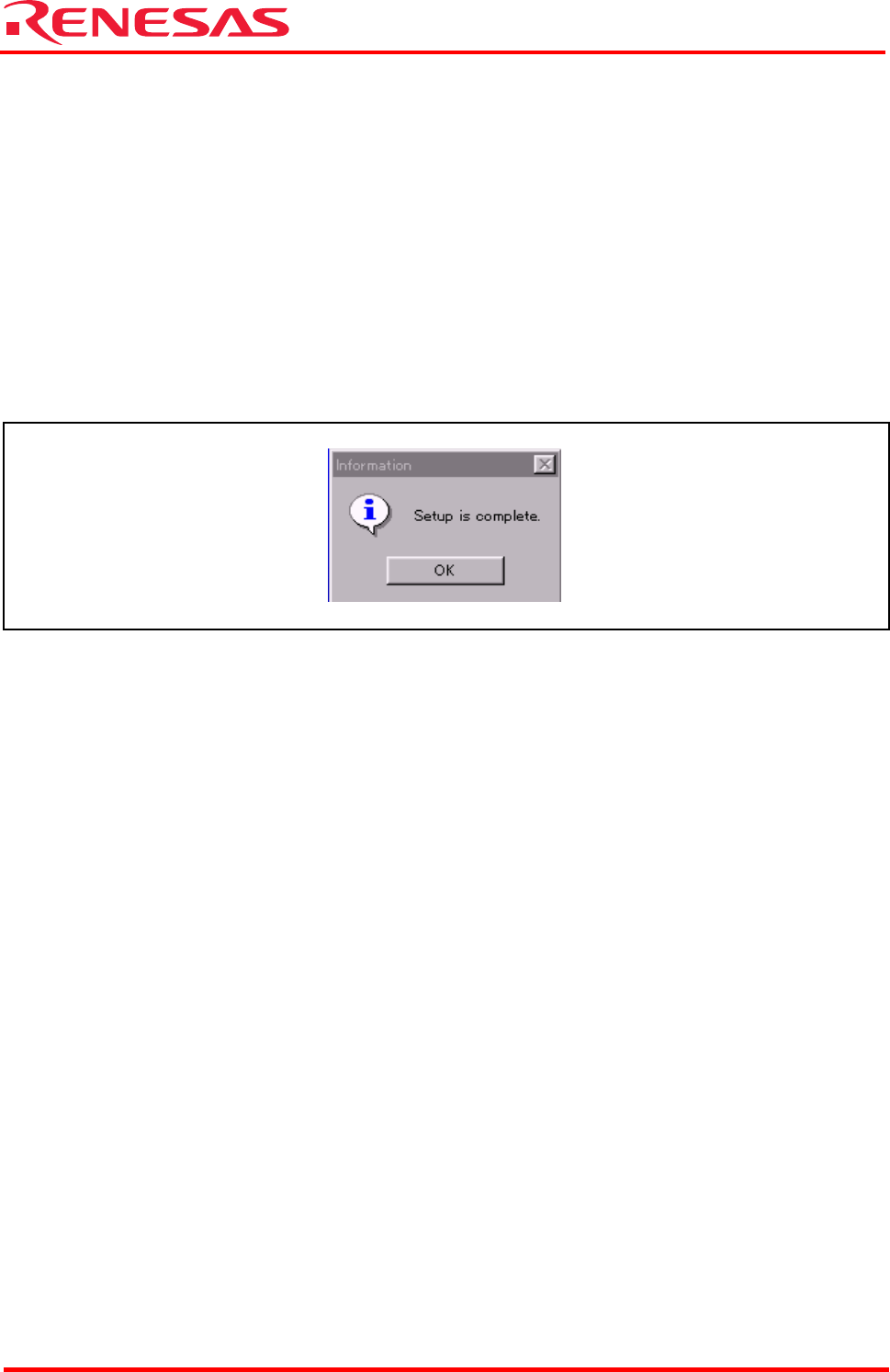
(3) When you finished installing M3S-KD32R, the dialog box shown in appears.
Figure 6.7 Dialog Box when Installation is Finished
(4) Case of using Windows 2000 / NT4.0, after M3S-KD32R is installed, reboot the PC.