
User manual


Table Of Contents
- Notes regarding these materials
- Precautions on Using The Product Described Herein
- For Inquiries About Product Contents or This Manual
- Preface
- Contents
- 1. Overview
- 2. Contents of the Product Package
- 3. Usage Precautions
- 4. Starter Kit Usage Conditions
- 5. Hardware Setup
- 6. Software Setup
- Appendix 1 Contents of CD-ROM
- Appendix 2 Part List
- Appendix 3 M3A-2152G02 Product Standards
- 1. Overview
- 2. Functional Specifications
- 2.1 Configuration of the Power Supply
- 2.2 FP Select Circuit
- 2.3 MOD Select Circuit
- 2.4 Serial I/O Interface
- 2.5 Oscillator Circuit
- 2.6 General-purpose Output Port LED Indicators
- 2.7 General-purpose Input Port Control Circuit
- 2.8 Analog Port Input Control Circuit
- 2.9 CAN Interface
- 2.10 JTAG Peripheral Circuit
- 3. Reference Data
- REVISION HISTORY
32176 Group
Starter Kit User’s Manual M3A-2152
REJ10B0224-0300/Rev.3.00 Jan. 2007 Page 13 of 82
5.1.2 M3A-2152 Evaluation Board Power Supply and Settings
The following shows how to set the M3A-2152 Evaluation Board.
Use a 5V DC power supply to feed power to the M3A-2152 Evaluation Board.
Use included 5V power supply cable to connect the 5V DC power supply and CN2 connector
included with the M3A-2152 Evaluation Board. The Connecting when Feeding Power to the
M3A-2152 Evaluation Board is shown in Figure 5.2.
Figure 5.2 Connecting when Feeding Power to the M3A-2152 Evaluation Board
Table 5.3 Jumper Settings before Shipmen
Jumper Name Jumper Settings Remarks
H1 Shorted between 1-2 Uses power from CN2 connector to AVCC power supply
Note: For detail about the power supply settings, refer to Appendix 3 M3A-2152G02 Product Standards
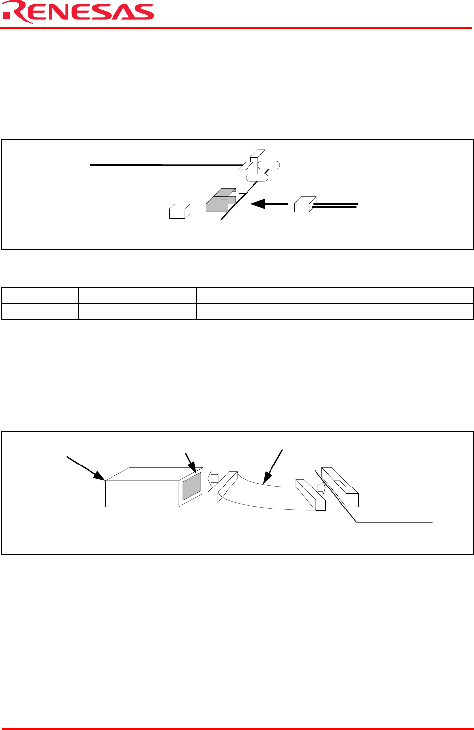
5.1.3 Connecting M3A-2152 Evaluation Board and M32100T-EZ-E
Use included 10-pin flat cable to connect M32100T-EZ-E and XCN1 connector included with the
M3A-2152 Evaluation Board.
The method for Connecting M3A-2152 Evaluation Board and M32100T-EZ-E is shown in Figure
5.3.
Figure 5.3 Connecting M3A-2152 Evaluation Board and M32100T-EZ-E
5.1.4 System Power-on Sequence when M3A-2152G52A in Use
- When turning on power, turn on M32100T-EZ-E first and then the M3A-2152 Evaluation
Board.
- When turning off power, turn off the M3A-2152 Evaluation Board first and then
M32100T-EZ-E.
- When turning on power again after turning off power, wait for 10 seconds.
- Power to M32100T-EZ-E can be fed from USB cable.
Note: Unless the Starter Kit is powered on this sequence, the kit may operate erratically or break down.
4.75 - 5.25V DC power supply
M3A-2152 evaluation board
CN2
H1
M3A-2152 evaluation board
XCN1
10-pin flat cable
M32100T-EZ-E
SDI I/F