
User manual


Table Of Contents
- Notes regarding these materials
- Precautions on Using The Product Described Herein
- For Inquiries About Product Contents or This Manual
- Preface
- Contents
- 1. Overview
- 2. Contents of the Product Package
- 3. Usage Precautions
- 4. Starter Kit Usage Conditions
- 5. Hardware Setup
- 6. Software Setup
- Appendix 1 Contents of CD-ROM
- Appendix 2 Part List
- Appendix 3 M3A-2152G02 Product Standards
- 1. Overview
- 2. Functional Specifications
- 2.1 Configuration of the Power Supply
- 2.2 FP Select Circuit
- 2.3 MOD Select Circuit
- 2.4 Serial I/O Interface
- 2.5 Oscillator Circuit
- 2.6 General-purpose Output Port LED Indicators
- 2.7 General-purpose Input Port Control Circuit
- 2.8 Analog Port Input Control Circuit
- 2.9 CAN Interface
- 2.10 JTAG Peripheral Circuit
- 3. Reference Data
- REVISION HISTORY
32176 Group
Starter Kit User’s Manual M3A-2152
REJ10B0224-0300/Rev.3.00 Jan. 2007 Page 12 of 82
5. Hardware Setup
This chapter describes how to set up the hardware components necessary to use the Starter Kit.
Table 5.1 and Table 5.2 show how to set up the hardware components.
Table 5.1 Hardware Setup Procedure
When connected to the emulator
When using the evaluation
board by itself
Setup Procedure
M3A-2152G52A M3A-2152G52 M3A-2152G52A/M3A-2152G52
Set the emulator 1st (Refer to 5.1.1) 1st (Refer to 5.2.1)—
Connect the host PC and emulator 2nd (Refer to 5.1.1) 2nd (Refer to 5.2.2)—
Set the evaluation board 3rd (Refer to 5.1.2) 3rd (Refer to 5.2.3) 1st (Refer to 5.3.1)
Connect the evaluation board and
emulator
4th (Refer to 5.1.3) 4th (Refer to 5.2.4)—
Turn on the emulator 5th (Refer to 5.1.4) 5th (Refer to 5.2.5)—
Turn on the evalution board 6th (Refer to 5.1.4) 6th (Refer to 5.2.5) 2nd (Refer to 5.3.2)
Table 5.2 Hardware Power Off Procedure
Setup Procedure When connected to the emulator
When using the evaluation
board by itself
Turn off the evaluation board. 1st (Refer to 5.1.4) 1st (Refer to 5.3.2)
Turn off the emulator. 2nd (Refer to 5.1.4) —
5.1 Hardware Setup when M3A-2152G52A in Use
5.1.1 M32100T-EZ-E Power Supply and Settings
The following shows how to set M32100T-EZ-E.
For more details, refer to M32100T-EZ-E User’s Manual.
M32100T-EZ-E is supplied power from the host PC via USB cable, and it turns ON by connecting
included USB cable.
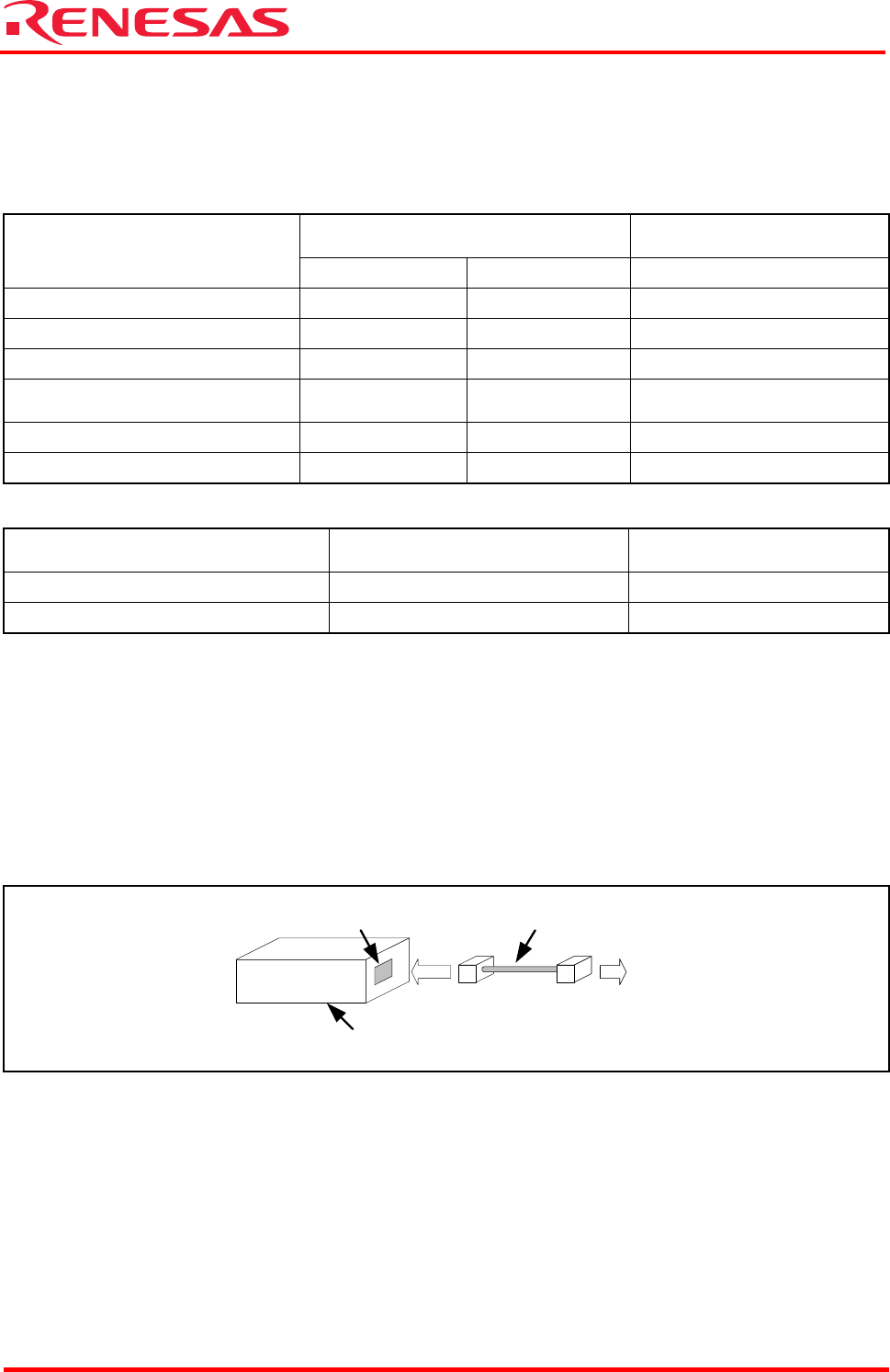
The Connecting M32100T-EZ-E and Host PC is shown in Figure 5.1
Figure 5.1 Connecting M32100T-EZ-E and Host PC
USB cable
M32100T-EZ-E
USB I/F
Connect to the host
PC’s USB port