
User manual


Table Of Contents
- Notes regarding these materials
- Precautions on Using The Product Described Herein
- For Inquiries About Product Contents or This Manual
- Preface
- Contents
- 1. Overview
- 2. Contents of the Product Package
- 3. Usage Precautions
- 4. Starter Kit Usage Conditions
- 5. Hardware Setup
- 6. Software Setup
- Appendix 1 Contents of CD-ROM
- Appendix 2 Part List
- Appendix 3 M3A-2152G02 Product Standards
- 1. Overview
- 2. Functional Specifications
- 2.1 Configuration of the Power Supply
- 2.2 FP Select Circuit
- 2.3 MOD Select Circuit
- 2.4 Serial I/O Interface
- 2.5 Oscillator Circuit
- 2.6 General-purpose Output Port LED Indicators
- 2.7 General-purpose Input Port Control Circuit
- 2.8 Analog Port Input Control Circuit
- 2.9 CAN Interface
- 2.10 JTAG Peripheral Circuit
- 3. Reference Data
- REVISION HISTORY
32176 Group
Starter Kit User’s Manual M3A-2152
REJ10B0224-0300/Rev.3.00 Jan. 2007 Page 10 of 82
3.6 About Evaluation Board
When the evaluation board does not start operation after supplied power, check the following
points.
3.6.1 Contact failure of IC Socket
Oscillation or thermal expansion may cause a poor connection between microcomputers and IC
socket on the Evaluation Board. Follow the steps below.
- Screw down the top cover of IC socket with setscrews at four corners.
The tightening torque shall be 0.054 N.m.
Note that only one tight setscrew may cause a poor connection.
The IC socket included in the evaluation board uses NQPACK and HQPACK by TOKYO
ELETECH CORPORATION.
For more details, visit their website at http://www.tetc.co.jp/e_index.htm.
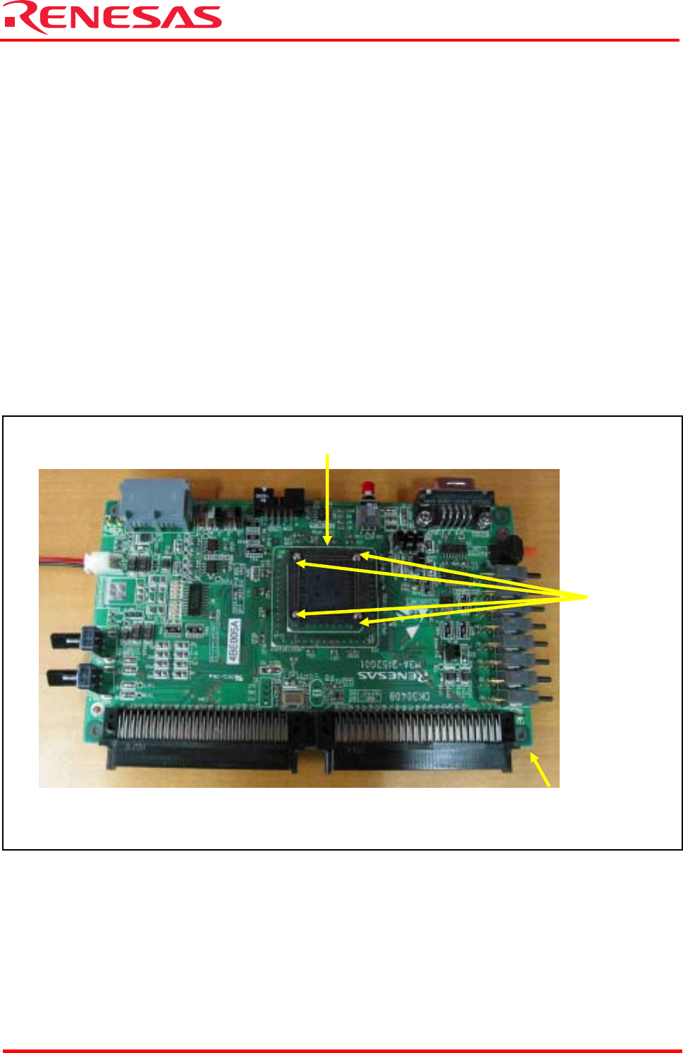
The following illustrates configuration of M3A-2152G02 (32176 Group Evaluation Board).
Figure 3.2 M3A-2154G02A
3.6.2 Cable Connection
- Make sure the cables are connected to the evaluation board firmly.
IC socket (HQPACK)
32176 group evaluation
board M3A-2152G02
Setscrews on
cover of
IC socket