REJ10J0972-0100(T) M34571T2-CPE User's Manual Compact Emulator for 4571 Group Rev.1.00 Feb.
Keep safety first in your circuit designs! 1. Renesas Technology Corp. puts the maximum effort into making semiconductor products better and more reliable, but there is always the possibility that trouble may occur with them. Trouble with semiconductors may lead to personal injury, fire or property damage.
M34571T2-CPE User’s Manual Preface Preface The M34571T2-CPE is a compact emulator for the 4571 Group MCUs with the real-time trace function. This user's manual mainly describes specifications of the M34571T2-CPE compact emulator and how to setup it. For details on the following products included with the M34571T2-CPE, refer to each product's online manual. Emulator debugger: Assembler: M3T-PD45M ASM45 All the components of this product are shown in "1.1 Package Components" (page 13).
M34571T2-CPE User’s Manual Important Important Before using this product, be sure to read this user’s manual carefully. Keep this user’s manual, and refer to this when you have questions about this product. Emulator: The emulator in this document refers to the following products that are manufactured by Renesas Technology Corp.: (1) Compact emulator main unit (2) Package converter board for connecting the user system The emulator herein does not include the customer’s user system and host machine.
M34571T2-CPE User’s Manual Important Usage restrictions: This emulator has been developed as a means of supporting system development by users. Therefore, do not use it as a device used for equipment-embedded applications.
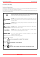
M34571T2-CPE User’s Manual Precautions for Safety Precautions for Safety Definitions of Signal Words In both the user’s manual and on the product itself, several icons are used to insure proper handling of this product and also to prevent injuries to you or other persons, or damage to your properties. This chapter describes the precautions which should be taken in order to use this product safely and properly. Be sure to read this chapter before using this product.
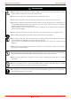
M34571T2-CPE User’s Manual Precautions for Safety WARNING Warnings for AC Power Supply: If the attached AC power cable does not fit the receptacle, do not alter the AC power cable and do not plug it forcibly. Failure to comply may cause electric shock and/or fire. Use an AC power cable which complies with the safety standard of the country. Do not touch the plug of the AC power cable when your hands are wet. This may cause electric shock. This product is connected signal ground with frame ground.
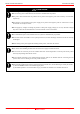
M34571T2-CPE User’s Manual Precautions for Safety CAUTION Notes on Connecting the Power Supply of the Emulator: Do not use any power cable other than the one that is included with the product. The power cable included with the product has its positive and negative poles color-coded by red and black, respectively. Pay attention to the polarities of the power supply. If its positive and negative poles are connected in reverse, the internal circuit may be broken.
M34571T2-CPE User’s Manual Contents Contents Page Preface..........................................................................................................................................................................3 Important.......................................................................................................................................................................4 Precautions for Safety ................................................................................
M34571T2-CPE User’s Manual Contents Page 3. Usage (How to Use the Emulator Debugger) .........................................................................................................41 3.1 Starting Up the Emulator Debugger (Init Dialog Box) ...................................................................................41 3.2 Program Window ...........................................................................................................................................43 3.
M34571T2-CPE User’s Manual User Registration User Registration When you have purchased the emulator presented in this user's manual, please be sure to register it. As the H/W Tool Customer Registration Sheet is included with this manual, fill it in and email the same contents to the following address. Your registered information is used for only after-sale services, and not for any other purposes.
M34571T2-CPE User’s Manual Terminology Terminology Some specific words used in this user’s manual are defined as follows: Emulator M34571T2-CPE This means the compact emulator (this product) for 4571 Group MCUs. Emulator system This means an emulator system built around the M34571T2-CPE emulator. The M34571T2-CPE emulator system is configured with an emulator main unit M34571T2-CPE, emulator debugger M3T-PD45M and host machine.
M34571T2-CPE User’s Manual 1. Outline 1. Outline This chapter describes the package components, the system configuration and the preparation for using this product for the first time. 1.1 Package Components The M34571T2-CPE package consists of the following items. When unpacking it, check to see if your M34571T2-CPE contains all of these items. Table 1.
M34571T2-CPE User’s Manual 1. Outline 1.2 System Configuration 1.2.1 System Configuration Figure 1.1 shows a configuration of the M34571T2-CPE system. Power supply for emulator (not included) Power supply cable USB interface cable Power supply for user system (not included) Host machine Compact emulator (not included) M34571T2-CPE Pitch converter board User system Figure 1.
M34571T2-CPE User’s Manual 1. Outline (5) Power supply for the user system This is a power supply for the user system. As this emulator cannot supply the power to the user system, supply the power to the user system separately from the emulator. (6) Host machine This is a personal computer for controlling the emulator. (7) Pitch converter board This is a pitch converter board for connecting to an MCU foot pattern on the user system. For details, refer to “2.8 Connecting the User System” (page 31).
M34571T2-CPE User’s Manual 1. Outline 1.2.2 Names and Functions of each part of the Emulator Figure 1.2 shows the names of the LEDs on the upper panel of the emulator. Check pins TP1: VDD2 TP2: GND TP3: WRST SW1 5V 3V WRST LED1 T XE 3.3V 5.
M34571T2-CPE User’s Manual 1. Outline (3) POF Status LED This LED shows whether the MCU is in a state of POF Table 1.4 Definitions of the target status LEDs Name Color POF Orange Status ON OFF Meaning MCU is in a state of POF MCU is not in a state of POF, but normal. (4) System Reset Switch By pressing the system reset switch, you can initialize the emulator system. Table 1.5 shows the functions of the system reset switch depending on the state of the emulator. Table 1.
M34571T2-CPE User’s Manual 1. Outline 1.3 Specifications Table 1.6 lists specifications of the M34571T2-CPE. Table 1.6 M34571T2-CPE specifications Applicable MCUs Evaluation MCU Maximum operating frequency Applicable power supply Basic debugging functions Real-time trace function 4571 Group M34571GDFP (mounted in the socket of the emulator) 3.0 V Divided-by 8-mode Set the MCU power supply voltage selection switch Divided-by 4-mode (SW1) to 3V. Divided-by 2-mode Through mode 5.
M34571T2-CPE User’s Manual 1. Outline 1.4 Operating Environment Be sure to use thins emulator with the operating environmental of the emulator and host machine listed in Tables 1.7 and 1.8. Table 1.7 Operating environmental conditions Item Operating temperature Storage temperature Description 5 to 35°C (no dew) -10 to 60°C (no dew) Table 1.8 Operating environment of the host machine Item Host machine OS CPU Memory Pointing device such as mouse CD drive Description IBM PC/AT compatibles with USB1.
M34571T2-CPE User’s Manual 2. Setup 2. Setup This chapter describes the preparation for using this product, the procedure for starting up the emulator and how to change settings. 2.1 Flowchart of Starting Up the Emulator The procedure for starting up the emulator is shown in Figure 2.1. For details, refer to each section hereafter. And, when the emulator does not start up normally, refer to “5. Troubleshooting” (page 65). Check the package components. Refer to “1.1 Package Components (page 13).
M34571T2-CPE User’s Manual 2. Setup 2.2 Installing the Emulator Debugger If the OS used in your host machine is Windows XP or 2000, this installation must be executed by a user with administrator rights. Be aware that users without administrator rights cannot complete the installation. 2.2.1 Installing the Emulator Debugger M3T-PD45M From the CD-ROM included with your product, install the emulator debugger M3T-PD45M following the procedure described below.
M34571T2-CPE User’s Manual 2. Setup 2.3 Connecting the Power Supply for the Emulator Connect the power supply for the emulator to the power connector (J1). The specification of the power supply for the emulator is listed in Table 2.1. Table 2.1 Specification of power supply of the emulator DC 5.0 V±5%/2 A Power supply voltage Figures 2.2 and 2.3 show the specifications of the power connector (J1) and an applicable plug, respectively. Electrode (+) Electrode (-) φ1.7mm(Inside diameter) φ4.
M34571T2-CPE User’s Manual 2. Setup 2.4 Connecting the Host Machine 5V SW1 3V POF LED1 GND TP2 WRST J3 13 14 STATUS IN JAPAN MADE COMPACTMADE EMULATOR LED6 RUN LED3 POWER CLOCK TARGET RESET STATUS RUN RESE T POWER C LOCK POWER SYSTEM SAFE STATUS COMPACT EMULATOR 1 26 M34571T2-CPE POWER USB 5.0V LED2 4 SAFE D 5 EL LED1 POWER J4 DEL 3.3V 5.0V b To emulator power supply Connect the power cable to connector J1.
M34571T2-CPE User’s Manual 2. Setup 2.5 Turning ON the Power 2.5.1 MCU Power Supply Voltage Selection Switch Set the MCU power supply source selection switch of the emulator according to conditions of use. 5V SW1 3V POF LED1 PJ 2 PJ 1 T NI T XE 3.3V 5.0V J3 13 14 STATUS POWER SAFE LED6 RUN RESET CLOCK POWER LED3 POWER CLOCK TARGET RESET STATUS RUN IN JAPAN MADE COMPACTMADE EMULATOR 1 26 M34571T2-CPE COMPACT EMULATOR POWER SYSTEM SAFE STATUS LED2 4 SAFE D 5EL POWER USB 5.
M34571T2-CPE User’s Manual 2. Setup 2.5.2 Checking Connections of the Emulator System Before turning the power ON, check the connection of the interface cable to the host machine, emulator, and user system. 2.5.3 Turning ON/OFF the Power Turn ON/OFF the power of the emulator and user system as simultaneously as possible. Do not leave either the emulator or user system powered on, because of leakage current the internal circuits may be damaged.
M34571T2-CPE User’s Manual 2. Setup 2.5.5 LED Display When the Emulator Starts Up Normally 5V 3V POF EL D1 SW1 J4 J3 13 14 POWER SAFE STATUS M34571T2-CPEB REV.A RUN RESET LED3 POWER LED6 POWER CLOCK TARGET RESET STATUS RUN IN JAPAN MADE COMPACTMADE EMULATOR 1 26 M34571T2-CPE COMPACT EMULATOR SSA A FFEE LED2 LED2 DELLED 5DEL ED4 4 C LOCK CLOCK JP2 5 .0V POWER SYSTEM SAFE STATUS EXT3.3V POWER USB 5.
M34571T2-CPE User’s Manual 2. Setup When the user system NOT connected: The POWER LED does not light. POWER LED 3 CLOCK LED4 RESET LED5 RUN LED6 : ON : OFF Figure 2.7 Target status LEDs display when the emulator starts up normally (when user system not connected) When the user system connected: If the POWER LED does not light, shut off the system and check the setting of the jumper switches and if the power is properly supplied to the user system.
M34571T2-CPE User’s Manual 2. Setup 2.6 Downloading Firmware 2.6.1 When It is Necessary to Download Firmware It is necessary to download the firmware when: (1) the firmware has been upgraded (2) the emulator debugger M3T-PD45M has been upgraded If downloading firmware is not completed in the cases below, redownload the firmware. - When the power is unexpectedly shut down during a download from the emulator debugger - When a communications interface cable is unexpectedly pulled out 2.6.
M34571T2-CPE User’s Manual 2. Setup 2.7 Self-check 2.7.1 Self-check Procedure To run the self-check of the emulator, do so as explained here below. While the self-check is in progress, the LEDs will change as shown in Figure 2.9. (1) (2) (3) (4) (5) If the user system is connected, disconnect it. Set the switches as the factory-settings to execute the self-check (see Table 2.3). Within 2 seconds of activating power to the emulator, press the system reset switch on the emulator upper panel.
M34571T2-CPE User’s Manual 2. Setup 2.7.2 If an Error is Detected in the Self-check Table 2.4 lists how to remedy the troubles if the target status LED display is abnormal in the self-check. When an error is detected, shut off the emulator and the user system and follow the steps in the Table 2.4. Table 2.4 Error display in the self-check and how to remedy it LED display Problem & Remedy Blinking POWER CLOCK OFF RESET RUN The emulator system is not working properly.
M34571T2-CPE User’s Manual 2. Setup 2.8 Connecting the User System Figure 2.10 shows the connection of the M34571T2-CPE and the user system. 26-wire normal-pitch cable *1 For 26-pin DIP FFC-26BSM1 *2 *1 26-wire normal-pitch cable is included with the product. *2 Not included. Prepare it separately. FFC-26BSM1 is made by Honda Tsushin Kogyo Co., Ltd. Figure 2.
M34571T2-CPE User’s Manual 2. Setup 2.8.1 Connecting to a 2.54-mm-pitch Dual in-line Pins Here following is a procedure of connecting 2.54-mm-pitch 26-pole dual in-line pins using a 26-wire normal-pitch cable (included with the M34571T2-CPE). Table 2.5 lists the connector assignment of the 26-wire normal-pitch cable and Figure 2.11 shows the pin assignment of the 26-wire normal-pitch cable. 5V SW1 3V POF LED1 JP1 INT J P2 EXT3.3V 5.0V 2.54 J3 2.
M34571T2-CPE User’s Manual 2. Setup Table 2.5 Connector assignments of the 26-wire normal-pitch cable Connector pin Connector pin MCU pin No. Signal MCU pin No. Signal No. No.
M34571T2-CPE User’s Manual 2. Setup 2.9 Changing Settings 2.9.1 Changing the Power Supply Voltage to the MCU As shown in Table 2.6 below, set the switch according to the connection to the user system. Table 2.6 Setting switch MCU power supply voltage selection switch (SW1) 3V 5V Description Supplied from the emulator. The MCU operating voltage is 3 V. Supplied from the emulator. The MCU operating voltage is 5 V.
M34571T2-CPE User’s Manual 2. Setup 2.9.2 Selecting Clock Supply This product always uses the internal oscillator circuit as a clock supply to the evaluation MCU. 3V 5V SW1 POF J P2 E XT 3.3V 5.0V POWER USB 5.0V LED1 J P1 I NT J4 LED3 J3 13 14 POWER SAFE STATUS COMPACTMADE EMULATOR IN JAPANMADE POWER CLOCK TARGET RESET STATUS RUN COMPACT EMULATOR 1 26 M34571T2-CPE The oscillator circuit board of the emulator is placed as described on the left.
M34571T2-CPE User’s Manual 2. Setup 3. Using the Internal Oscillator Circuit Bare Board To use this product at a frequency you like, build a desired oscillator circuit on the included OSC-2 oscillator circuit bare board. Figure 2.13 shows an external view of the OSC-2 oscillator circuit bare board and the connector pin locations. Figure 2.14 shows the circuitry of the oscillator circuit bare board OSC-2. Use the number of oscillator circuits recommended by the oscillator manufacturer.
M34571T2-CPE User’s Manual 2. Setup 2.10 Connecting the External Trace/Trigger Cable Using the external trace/trigger cable enables record/reference a hardware break by the external trigger, and changes of an external signal level in the trace window 2.10.
M34571T2-CPE User’s Manual 2. Setup 2.10.3 Specifications of the External Trace/Trigger Cable Voltage input characteristics of external trace input and external trigger input are as follows. Table 2.7 Input characteristics of the external trace cable Item Input voltage “H” level input voltage “L” level input voltage Symbol VIN VIH VIL Min. 0V 2.0V - Max. 5.5V 0.8V External trace input is latched in the timing shown in Figure 2.17, and external trigger input is latched in the timing shown in Figure 2.
M34571T2-CPE User’s Manual 2. Setup 2.11 Watchdog Timer Initialization Cycle Check Pin The watchdog time cannot be used with this emulator system. The watchdog timer initialization cycle can be verified by observing the waveform at the check pin (WRST) of the emulator. 2.11.1 Check Pin WRST (TP3) on the Emulator Main Unit Figure 2.19 shows the positions of the check pins WRST (TP3) and GND (TP2).
M34571T2-CPE User’s Manual 2. Setup 2.11.2 Output Waveform of the Check Pin WRST A waveform similar to the one shown in Figure 2.20 is output when executing the WRST instruction hat initializes the watchdog timer. By observing a period in which the check pin (WRST) is goes high, it is possible to know when the watchdog timer is initialized. Instruction Next instruction WRST instruction Machine cycle T1 T2 T3 T1 T2 T3 XIN WRST (TP3) Figure 2.
M34571T2-CPE User’s Manual 3. Usage (How to Use the Emulator Debugger) 3. Usage (How to Use the Emulator Debugger) This chapter describes how to start up the emulator debugger and how to use the major windows. 3.1 Starting Up the Emulator Debugger (Init Dialog Box) To launch the emulator debugger, click the Start menu of Windows and then select Programs (P) >> [Renesas] >> [PD45M V.xx.xx Release x] >> [PD45M]. When the emulator debugger started up, the Init dialog box appears.
M34571T2-CPE User’s Manual 3. Usage (How to Use the Emulator Debugger) (2) Setting the Init dialog box (2/2) By pressing [OK] after setting the Init dialog box (1/2), the following Init dialog box will be displayed. Specifying the MCU file Specify the MCU to be debugged. REJ10J0972-0100 Rev.1.
M34571T2-CPE User’s Manual 3. Usage (How to Use the Emulator Debugger) 3.2 Program Window (1) Downloading a program 1. Initial screen of the program window Initial screen of the program window The program window is a window that always shows the content of the source file corresponding to the current position of the program counter. It automatically opens when the emulator starts up. The program counter position is identified by the yellow background color.
M34571T2-CPE User’s Manual 3. Usage (How to Use the Emulator Debugger) (2) Executing the program 1. Resetting the user program RESET Resets the program. 2. Executing the user program GO Executes the program from the current PC position. STEP Executes one step from the current PC position.. OVER Executes one over-step from the current PC position.. RETURN Executes the program up to the high-order subroutine. 3. Stopping the user program STOP Stops the program. 4.
M34571T2-CPE User’s Manual 3. Usage (How to Use the Emulator Debugger) (3) Setting breakpoints 1. Screen after breakpoint setup Breakpoint setup screen There are two types of breakpoints as described below. It is necessary to select the breakpoint by the break mode button. The current breakpoint is displayed in the break mode display area. BM:SW Software break mode BM:HW Hardware break mode .
M34571T2-CPE User’s Manual 3. Usage (How to Use the Emulator Debugger) (4) Executing up to the cursor position (Come command) 1. Specifying the Come command Setup procedure for executing COME command (1) Click the line in the program display area at which you want the program to execute. (2) Click the Come button. Click the line in the program display area at which you want the program to execute. 2. After the Come command has finished REJ10J0972-0100 Rev.1.
M34571T2-CPE User’s Manual 3. Usage (How to Use the Emulator Debugger) 3.3 Hardware Breakpoint Setting Window (1) Breakpoint setup dialog box 1. Opening the hardware breakpoint setup dialog box Hardware Break Point Clicking this button opens the hardware breakpoint setup dialog box. 2. Hardware Break Point Setting Window in initial state Hardware breakpoint setup dialog box You can use a combination of address event (A1 or A2) and T (external trigger event) as a hardware break event.
M34571T2-CPE User’s Manual 3. Usage (How to Use the Emulator Debugger) (2) Setting the combinatorial event condition 1. Window for setting the combinatorial event condition Setting the combinatorial event condition Select a combinatorial condition for A1, A2, and T. One of the following three combinatorial conditions can be selected.. - AND All of the specified conditions are met. - OR One of the specified conditions is met. - Sequential The specified conditions are met sequentially in a specified order.
M34571T2-CPE User’s Manual 3. Usage (How to Use the Emulator Debugger) 3.4 Trace Window (1) Trace window 1. Trace window Menu Windows Menu item Trace Window Function Opens the trace window. Trace window The trace window is used to show the results of real-time trace measurements. It has the following three display modes: - Bus mode Bus information per cycle can be inspected. The contents are displayed in order of execution paths.
M34571T2-CPE User’s Manual 3. Usage (How to Use the Emulator Debugger) 2. Trace window (bus display) Explanation of the trace window (bus display) Bus Display (BUS) The following explains the displayed contents, from left to right. - Address Shows the status of the address bus. - Data Shows the status of the data bus. - Areg Shows the status of the register A. - Skip When marked by 1, it means a skipped instruction. - Int When marked by 1, it means an interrupt has occurred.
M34571T2-CPE User’s Manual 3. Usage (How to Use the Emulator Debugger) (2) Trace point setup dialog box Opening the trace point setup dialog box Menu Menu item Function Debug Trace Point Setting the trace point dialog box 1. Setting the trace point dialog box Trace point setup dialog box You can use a combination of address event (A1 or A2) and external trigger event (T) as a trace event. Setting an address event By selecting A1 or A2, the address event dialog box will be displayed.
M34571T2-CPE User’s Manual 3. Usage (How to Use the Emulator Debugger) (3) Setting the combinatorial event condition 1. Window for setting the combinatorial event condition Setting the combinatorial event condition Select a combinatorial condition for A1, A2, and T. One of the following three combinatorial conditions can be selected.. - AND All of the specified conditions are met. - OR One of the specified conditions is met. - Sequential The specified conditions are met sequentially in a specified order.
M34571T2-CPE User’s Manual 3. Usage (How to Use the Emulator Debugger) 3.5 Time Measurement (1) Trace window 1. Setting time measurement points Menu Debug Menu item Measurement Point Function Sets up the time measurement points dialog box. Setting time measurement points A time measurement range can be specified by selecting one of the following eight time intervals. 1.From Go to Break: From when the program starts running to when it stops. 2.
M34571T2-CPE User’s Manual 4. Hardware Specifications 4. Hardware Specifications This chapter describes specifications of this product. 4.1 Target MCU Specifications Table 4.1 lists the specifications of target MCUs which can be debugged with this product. Table 4.
M34571T2-CPE User’s Manual 4. Hardware Specifications 4.2 Differences between the Actual MCU and Emulator Differences between the actual MCU and emulator are shown below. When debugging the MCU using this product, be careful about the following precautions. IMPORTANT Note on Differences between the Actual MCU and Emulator: Operations of the emulator system differ from those of actual MCUs as listed below.
M34571T2-CPE User’s Manual 4. Hardware Specifications IMPORTANT Note on Port Electrical Characteristics: Because the following ports are configured with port emulation circuits, electrical characteristics differ from those of the actual MCU. - P00--P03 - P10--P13 - P20--P21 - P30--P31 - D0--D3 -C -K - RESET# For more details, refer to “4.3 Connection Diagram” (page 59). The K, P20 and P21 pins, if pulled high in the user system, momentarily output a low after reset. This only occurs after reset.
M34571T2-CPE User’s Manual 4.
M34571T2-CPE User’s Manual 4. Hardware Specifications IMPORTANT Note on Register Operation: Tables 4.3 lists the registers that can be operated from the M3T-PD45M. The "Yes" in the table means that the register can be operated; the "No" means that the register can not be operated. Table 4.
M34571T2-CPE User’s Manual 4. Hardware Specifications 4.3 Connection Diagram Figure 4.2 shows a part of the connection diagram of the M34571T2-CPE. This connection diagram mainly shows the interface section. The circuits not connected to the user system such as the emulator's control system are omitted. The signals not shown in Figure 4.2 connect the evaluation MCU and the user system directly. Tables 4.4, 4.5, 4.6, 4.7, 4.8 and 4.9 show IC electric characteristics of this product for reference purposes.
M34571T2-CPE User’s Manual 4. Hardware Specifications Table 4.4 Electrical characteristics of the 74HC4050 Signal VIH VIL Item “H” level threshold voltage “L” level threshold voltage Standard values Min. Max. 1.50 3.15 4.20 0.50 1.35 1.80 Condition Vcc=2.0V Vcc=4.5V Vcc=6.0V Vcc=2.0V Vcc=4.5V Vcc=6.0V Unit V Table 4.5 Electrical characteristics of the 74ALS641A Signal VOL IOL Item “L” output voltage “L” output current Condition Vcc=4.5V, IOL=24mA Min. - Standard values Standard Max. 0.35 0.
M34571T2-CPE User’s Manual 4. Hardware Specifications Table 4.8 Electrical characteristics of the 74VHC14 Signal Item VP “H” level threshold voltage VN “L” level threshold voltage VH Hysteresis voltage Condition Vcc=3.0V Vcc=4.5V Vcc=5.5V Vcc=3.0V Vcc=4.5V Vcc=5.5V Vcc=3.0V Vcc=4.5V Vcc=5.5V Standard values Min. Max. 2.20 3.15 3.85 0.90 1.35 1.65 0.30 1.20 0.40 1.40 0.50 1.60 Unit V Table 4.
M34571T2-CPE User’s Manual 4. Hardware Specifications 4.4 External Dimensions 4.4.1 External Dimensions of the Compact Emulator Figure 4.3 shows external dimensions of the M34571T2-CPE. LED6 RUN RESET CLOCK LED3 5V SW1 3V POF LED1 J3 13 14 STATUS M34571T2-CPEB REV.A 25.0 POWER POWER SAFE POWER CLOCK TARGET RESET STATUS RUN COMPACTMADE EMULATOR IN JAPANMADE 1 26 M34571T2-CPE POWER SYSTEM SAFE STATUS COMPACT EMULATOR POWER USB 5.0V LED2 4 SAFE D5EL LED1 POWER J4 DEL EXT 3 .3V5 .
M34571T2-CPE User’s Manual 4. Hardware Specifications 4.5 Notes on Using This Product Notes on using this product are listed below. When debugging the MCU using this product, be careful about the following precautions. IMPORTANT Notes on the Self-check: If the self-check does not result normally (excluding target status errors), the emulator may be damaged. Then contact your local distributor. Run the self-check with the user system not connected.
M34571T2-CPE User’s Manual 4. Hardware Specifications IMPORTANT Note on the RAM Backup Mode: Although this emulator allows you to execute a program using POF instructions, execution of such programs is subject to the following limitations: The POF instruction cannot be stepped and over-stepped. Therefore, do not attempt to step and step-over the POF instruction. No events (hardware breaks and trace points) can be set in execution cycles of the POF instruction.
M34571T2-CPE User’s Manual 5. Troubleshooting 5. Troubleshooting This chapter describes how to troubleshoot when this product does not work properly. 5.1 Flowchart to Remedy the Troubles Figure 5.1 shows the flowchart to remedy the troubles from when power to the emulator is activated until the emulator debugger starts up. Check this while the user system is disconnected. For the latest FAQs visit the Renesas Tools Homepage. http://www.renesas.
M34571T2-CPE User’s Manual 5. Troubleshooting 5.2 When the Emulator Debugger Does Not Start Up Properly (1) When the LEDs of the M34571T2-CPE Do Not Display Normally Table 5.1 Errors LEDs show and their checkpoints 1 Error System Status POWER LED does not light up. Connection to the user system - Checkpoint Check that the power cable is connected. See “2.3 Connecting the Power Supply for the Emulator” (page 22). Table 5.
M34571T2-CPE User’s Manual 5. Troubleshooting (3) Program Window of the Debugger Does Not Appear Table 5.4 Checkpoints of errors at debugger startup (2/2) Error Checkpoint The PD45M version and the The firmware already installed in the PD45M is older in version than that installed version of firmware installed in the inside the emulator. target do not correspond to each - Download the latest firmware from the Web and install it securely. other. REJ10J0972-0100 Rev.1.
M34571T2-CPE User’s Manual 5. Troubleshooting 5.3 How to Request for Support After checking the items in "5 Troubleshooting", fill in the text file which is downloaded from the following URL, then send the information to your local distributor. http://tool-support.renesas.com/eng/toolnews/registration/support.
M34571T2-CPE User’s Manual 6. Maintenance and Guarantee 6. Maintenance and Guarantee This chapter describes how to maintenance, repair provisions and how to request for repair. 6.1 User Registration When you purchase our product, be sure register as a user. For user registration, refer to “User registration” (page 11) of this user's manual. 6.2 Maintenance (1) If dust or dirt collects on any equipment of your emulation system, wipe it off with a dry soft cloth.
M34571T2-CPE User’s Manual 6. Maintenance and Guarantee (3) Expiration of the repair period When a period of one year elapses after the model was dropped from production, repairing products of the model may become impossible. (4) Transportation fees at sending your product for repair Please send your product to us for repair at your expense. 6.5 How to Make Request for Repair If your product is found faulty, follow the procedure below to send your product for repair.
Compact Emulator for 4571 Group M34571T2-CPE User's Manual Publication Date: Feb. 10, 2006 Rev.1.00 Published by: Sales Strategic Planning Div. Renesas Technology Corp. Edited by: Microcomputer Tool Development Department Renesas Solutions Corp. © 2006. Renesas Technology Corp. and Renesas Solutions Corp., All rights reserved. Printed in Japan.
M34571T2-CPE User's Manual